Terminal equipment and its heat dissipation structure

A technology of terminal equipment and heat dissipation structure, which is applied in the field of electronics, can solve problems such as electromagnetic shielding performance and heat dissipation performance, and achieve the effects of ensuring electromagnetic shielding performance, ensuring heat dissipation performance, and improving heat dissipation performance

Active Publication Date: 2021-02-02
ZTE CORP
View PDF13 Cites 0 Cited by
  • Summary
  • Abstract
  • Description
  • Claims
  • Application Information

AI Technical Summary

Problems solved by technology

[0005] In view of this, the object of the present invention is to provide a terminal device and its heat dissipation structure to solve the technical problem that electromagnetic shielding performance and heat dissipation performance cannot be taken into account

Method used


Image

  • Terminal equipment and its heat dissipation structure
  • Terminal equipment and its heat dissipation structure
  • Terminal equipment and its heat dissipation structure

Examples


Embodiment Construction

[0023] In order to make the technical problems, technical solutions and beneficial effects to be solved by the present invention clearer and clearer, the present invention will be further described in detail below in conjunction with the accompanying drawings and embodiments. It should be understood that the specific embodiments described here are only used to explain the present invention, not to limit the present invention.

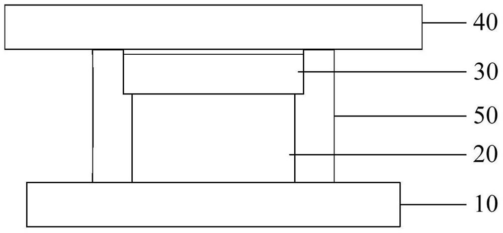
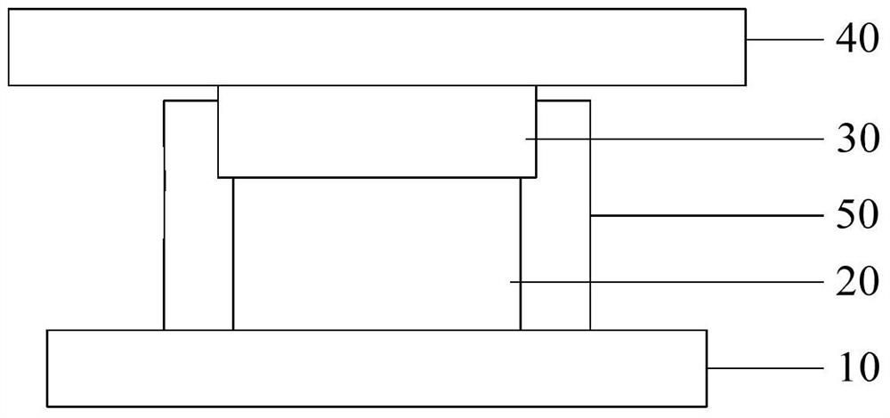
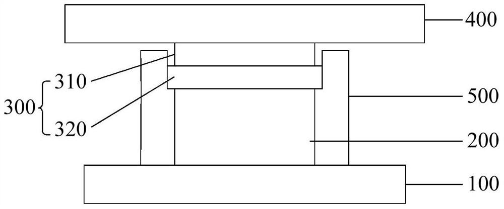
[0024] see image 3 , Figure 4 , the heat dissipation structure of the terminal equipment according to the embodiment of the present invention is proposed. The heat dissipation structure includes a substrate 100, a shielding frame 500, a casing 400, a heating element 200, and a heat conductor 300. The substrate 100, the heating element 200, the heat conductor 300, and the casing 400 The shielding frame 500 is arranged between the substrate 100 and the casing 400, and windows are opened at the upper and lower ends of the shielding frame 500, so that th...


PUM


Abstract

The invention discloses a terminal device and its heat dissipation structure, which belongs to the field of electronic technology. The heat dissipation structure includes a substrate, a heating element, a heat conductor, and a casing stacked sequentially from bottom to top, and a shielding frame arranged between the substrate and the casing , the base plate, the shielding frame and the shell enclose to form an accommodating space, the heating element and the heat conductor are accommodated in the accommodating space, the heat conductor at least includes a first heat conduction layer, and the first heat conduction layer is made of a heat conduction phase change material. Therefore, by filling the heat conductor with the first heat conduction layer made of heat-conducting phase-change material between the shell and the heating element, the heat conductor can dynamically adapt to the gap between the heat-generating element and the shell when the terminal is running . On the one hand, when the terminal is in working state, there is no gap between the shell and the shielding frame, which ensures the electromagnetic shielding performance; improved thermal performance.

Description

technical field [0001] The invention relates to the field of electronic technology, in particular to a terminal device and its heat dissipation structure. Background technique [0002] In the prior art, the heat dissipation structure of the mobile phone is as figure 1 , figure 2 As shown, it includes a substrate 10, a heating element 20, a thermal pad 30, a housing 40, and a shielding frame 50. The heating element 20 and the thermal pad 30 are accommodated in the housing space formed by the substrate 10, the shielding frame 50, and the casing 40, so as to Electromagnetic shielding of the heating element 20 is realized. The heating element 20 is arranged on the substrate 10 and has a certain gap with the housing 40. The thermal pad 30 is filled in the gap and fully contacts the heating element 20 and the housing 40 to transfer the heat of the heating element 20 to the housing 40. The heat is finally dissipated into the air through the housing 40 . [0003] The height dim...

Claims


Application Information

Patent Timeline
Patent Type & Authority Patents(China)
IPC IPC(8): H05K7/20H05K9/00
CPCH05K7/2029H05K9/002H04M1/02H05K7/20
Inventor 黄竹邻
Owner ZTE CORP
Why Eureka
Try Eureka