A locking mechanism for an electronic equipment chassis cover and its application method

A technology of electronic equipment and locking mechanism, which is applied in the direction of electrical equipment casing/cabinet/drawer, casing/cabinet/drawer parts, electrical components, etc., and can solve the problem of ineffective protection of electronic equipment safety, confidentiality circuit modules, etc. problems, to achieve the effect of facilitating equipment maintenance, ensuring electromagnetic shielding, and the appearance of the chassis is neat and beautiful

Active Publication Date: 2020-07-17
NO 34 RES INST OF CHINA ELECTRONICS TECH GRP
View PDF16 Cites 0 Cited by
  • Summary
  • Abstract
  • Description
  • Claims
  • Application Information

AI Technical Summary

Problems solved by technology

Anyone can open it arbitrarily, and it cannot effectively protect the circuit modules with safety and confidentiality requirements inside the electronic equipment.

Method used


Image

  • A locking mechanism for an electronic equipment chassis cover and its application method
  • A locking mechanism for an electronic equipment chassis cover and its application method
  • A locking mechanism for an electronic equipment chassis cover and its application method

Examples


Embodiment Construction

[0058] Embodiment of the locking mechanism for the cover plate of the case of electronic equipment

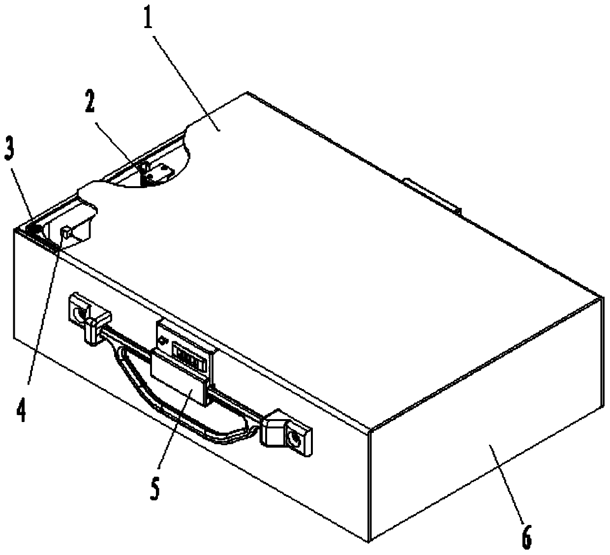
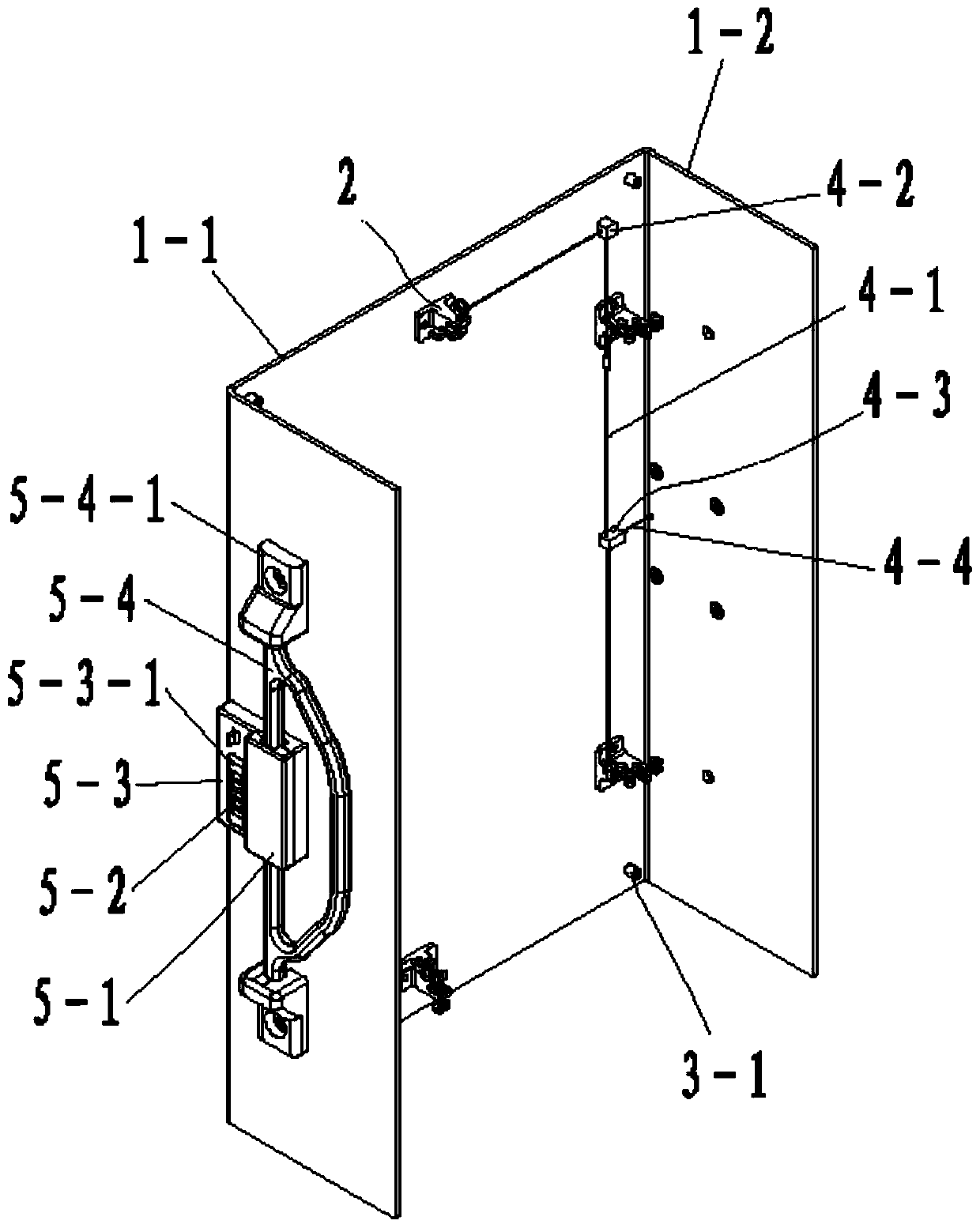
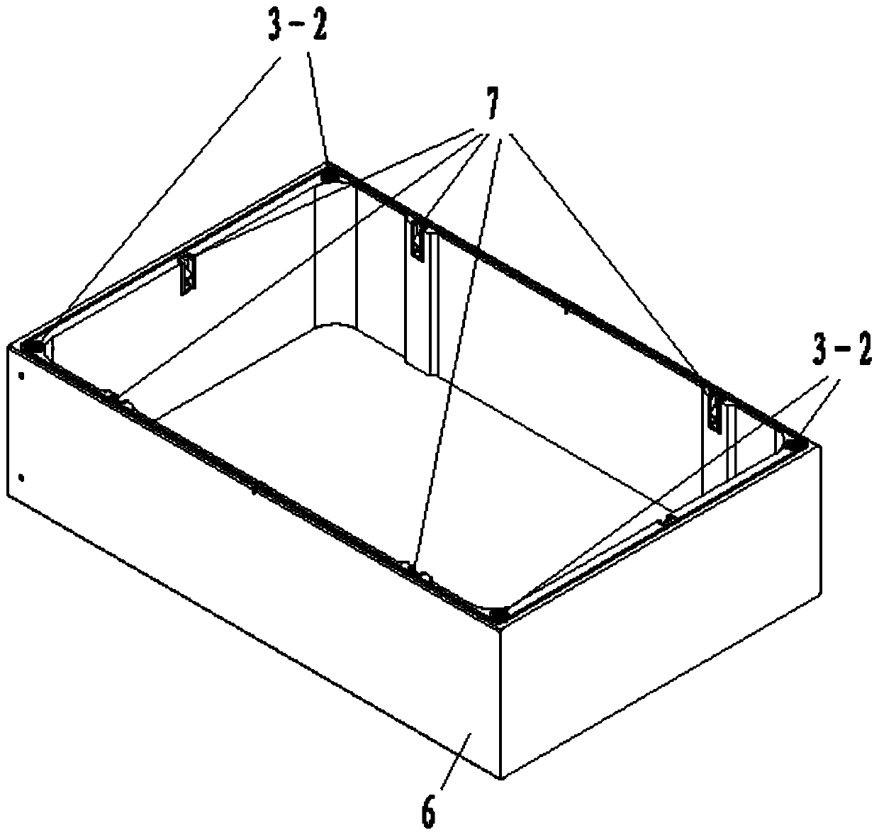
[0059] The appearance of the electronic equipment case after the cover plate 1 is locked in the locking mechanism embodiment of the cover plate of the electronic equipment case is as follows: figure 1 As shown, the specific structure is as Figures 2 to 4 As shown, the case of this example is a cuboid, and the casing 6 has 5 rectangular faces of the cuboid, and one rectangular face of the cuboid is closed by the cover plate 1 . The section of the cover plate 1 in this example is X-shaped, which is formed by bending the sheet material. The top of the X-shaped top is a rectangular top plate 1-1 matching the vacant rectangular surface of the cuboid, and the two sides of the top plate 1-1 are side plates perpendicular to the top plate 1-1. 1-2, the length and width of the side panels 1-2 of this example are the same as the length and width of the side walls of the box body 6 . Wh...


PUM


Abstract

The invention relates to a locking mechanism of an electronic device equipment case cover plate and a using method thereof. The locking mechanism of the cover plate is provided with a lock tongue assembly, a guide pin, a steel wire drive assembly and a locking assembly, wherein the lock tongue assembly and the guide pin correspond to a locking throat and a rebounder on the sidewall of an case bodyrespectively. Various lock tongues are connected in series to the U-shaped block of a locking block by a master steel wire, a transmission steel wire and a branch steel wire. A safety lock controls aslide block, and moves the slide block to drive the locking pin of a linkage into and out of the locking hole of the U-shaped block. When the cover plate is installed, the guide pin is aligned with the rebounder, the cover plate is pressed, and the lock tongues are inserted into the lock throat to be locked. When the cover plate is uninstalled, the safety lock is unlocked, the slide block is moved, the locking block is unlocked, a handle is rotated upward to be horizontal and then is pull outwards, the locking block is moved outwards, the mater steel wire, the transmission steel wire, and thebranch steel wire are pulled to synchronously drive the lock tongues connected in series to exit the lock throat, the rebounder opens the top plate, and the cover plate is removed. The locking mechanism does not need any tool, can quickly install and uninstall the cover plate of the equipment case, has good electromagnetic shielding performance, and also has a safety lock.

Description

technical field [0001] The invention relates to a case structure of an electronic device, in particular to a locking mechanism for a cover plate of the case of an electronic device and a using method thereof. Background technique [0002] The chassis of existing electronic equipment is required to be airtight and have an electromagnetic shielding function. [0003] At present, many covers of electronic equipment cases are assembled through card slots. The installation and disassembly are relatively simple, but the gap between the cover and the box is large, the electromagnetic shielding effect is not good, and electromagnetic leakage interferes with the normal operation of the equipment. [0004] There are also many case covers that are fastened and installed with screws, which have the function of electromagnetic shielding. However, the assembly of a large number of screws is cumbersome, which is not conducive to quick disassembly and assembly, and the assembly efficiency ...

Claims


Application Information

Patent Timeline
Patent Type & Authority Patents(China)
IPC IPC(8): H05K5/02
CPCH05K5/0221
Inventor 梁增柱王志勇韦海波李虔华刘霄海何立文
Owner NO 34 RES INST OF CHINA ELECTRONICS TECH GRP
Why Eureka
Try Eureka