A Novel Viscous Damper with Adjustable Damping Coefficient

A technology of viscous damper and damping coefficient, applied in shock absorbers, shock absorbers, solid shock absorbers, etc., can solve the problems of poor reliability, high cost, ineffective controllers and sensors, and achieve simple structure, low cost effect

Active Publication Date: 2020-04-14
NANTONG LANKE DAMPING TECH CO LTD
View PDF1 Cites 1 Cited by
  • Summary
  • Abstract
  • Description
  • Claims
  • Application Information

AI Technical Summary

Problems solved by technology

[0005] After adopting the above structure, the change of damping can be realized by using the oil pipe circuit and the pressure gauge, so as to realize the protection of the stroke, but the structure of this method is relatively complicated, the cost is high, and the power supply needs to be connected at all times, which cannot be measured due to earthquakes, strong winds, power supply damage and aging. Factors, controllers and sensors often fail, poor reliability

Method used


Image

  • A Novel Viscous Damper with Adjustable Damping Coefficient
  • A Novel Viscous Damper with Adjustable Damping Coefficient
  • A Novel Viscous Damper with Adjustable Damping Coefficient

Examples


Embodiment 1

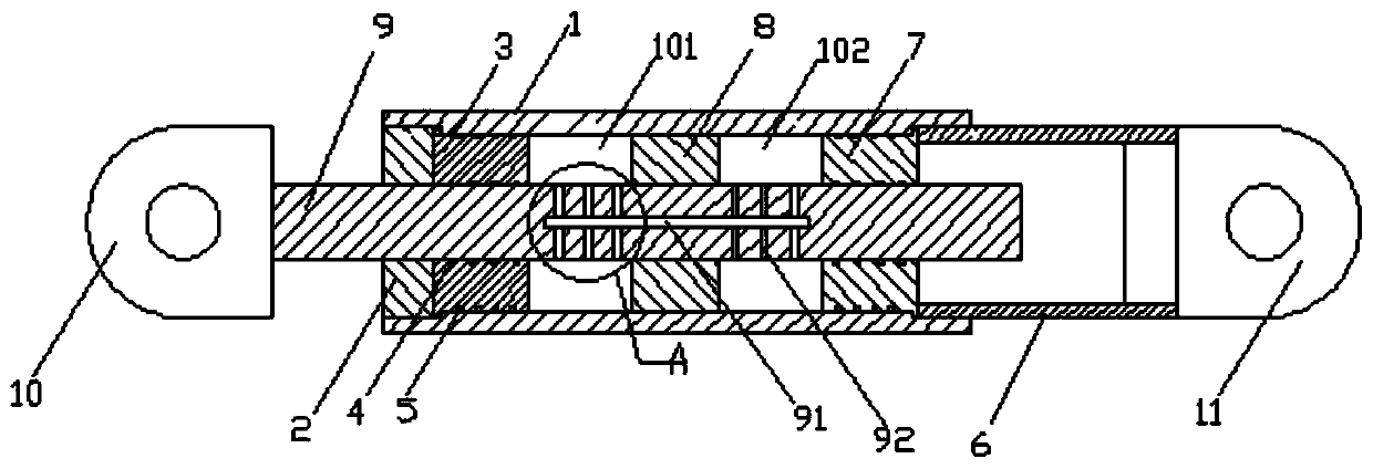
[0041] like figure 1 , figure 2 As shown, it is a new type of viscous damper with adjustable damping coefficient of the present invention, which consists of cylinder body 1, front end cover 2, front guide sleeve 3, dynamic seal 4, static seal 5, auxiliary cylinder 6, rear Cover 7, piston 8, piston rod 9, front earring 10 and rear earring 11 are formed;

[0042] The inner wall of the front end of the cylinder body 1 is provided with a first groove, and the front end cover 2 is fixed in the first groove, and the front guide sleeve 3 is arranged behind the front end cover 2, and the front guide sleeve 3 is arranged on the front end cover 2 to prevent the front The guide sleeve 3 moves forward, and the outer wall of the front guide sleeve 3 is provided with a first lug, and the first lug is engaged with the first groove to prevent the front guide sleeve 3 from moving backward. The seal 4, the outer wall of the front guide sleeve 3 is provided with a static seal 5, and the stati...

Embodiment 2

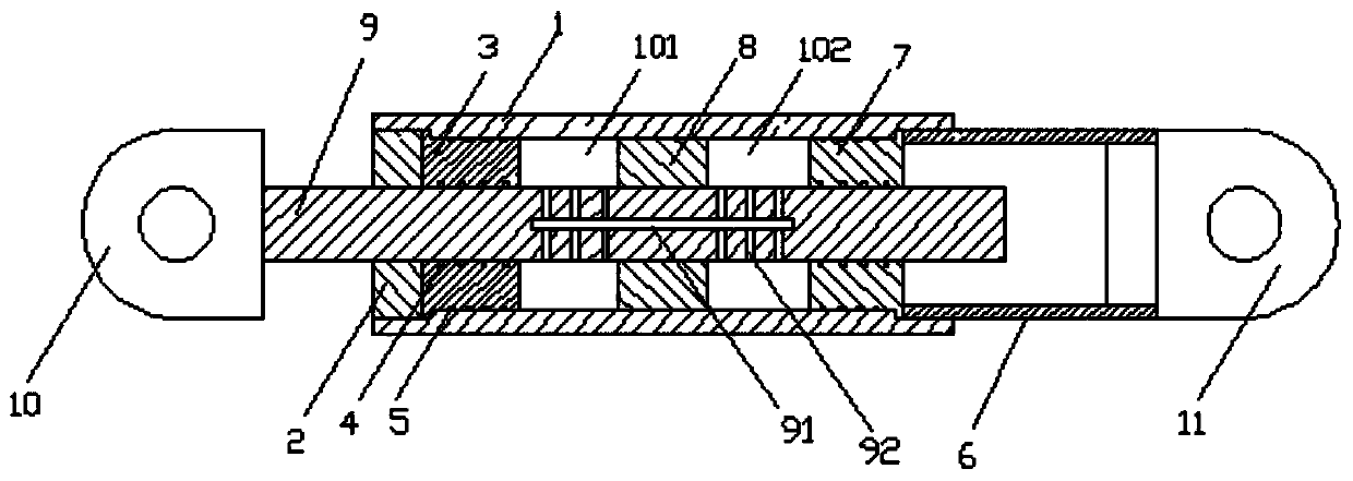
[0056] like Image 6 , Figure 7 As shown, it is another new viscous damper with adjustable damping coefficient of the present invention, which consists of a cylinder body 1, a front cover 2, a front guide sleeve 3, a dynamic seal 4, a static seal 5, an auxiliary cylinder 6, a rear Composed of guide sleeve 7, piston 8, piston rod 9, front earring 10 and rear earring 11;

[0057] The inner wall of the front end of the cylinder body 1 is provided with a first groove, and the front end cover 2 is fixed in the first groove, and the front guide sleeve 3 is arranged behind the front end cover 2, and the front guide sleeve 3 is arranged on the front end cover 2 to prevent the front The guide sleeve 3 moves forward, and the outer wall of the front guide sleeve 3 is provided with a first lug, and the first lug is engaged with the first groove to prevent the front guide sleeve 3 from moving backward. The seal 4, the outer wall of the front guide sleeve 3 is provided with a static seal...


PUM


Abstract

The invention discloses a novel viscous damper with an adjustable damping coefficient. The viscous damper comprises a cylinder body, a piston and a piston rod; the two ends of the cylinder body are provided with guide sealing mechanisms, the two ends of the piston rod are matched with the guide sealing mechanisms at the two ends of the cylinder body respectively, and the piston is arranged in themiddle of the piston rod; the piston rod drives the piston to move in the cylinder body, and the piston divides the cylinder body into a first space and a second space; a damping channel making the first space connected with the second space is formed in the piston rod, and a plurality of openings are formed in damping channel and in the portions, on the two sides of the piston, of the surface ofthe piston rod respectively; the openings are closed or opened by sealing elements along with the displacement of the piston. The viscous damper has the advantages of being simple in structure, low inmanufacturing cost and capable of achieving damping multi-stage adjustment without being connected with a power source.

Description

technical field [0001] The invention relates to a damper, in particular to a novel viscous damper with adjustable damping coefficient. Background technique [0002] Viscous damper is a speed-dependent damper, which was first used in machinery, military industry, aviation and other fields to control the vibration and shock of equipment. With the continuous advancement of technology, viscous dampers are gradually being extended to civil projects such as building structures and bridges to dissipate destructive energy caused by earthquakes and strong winds. The viscous damper mainly includes several technical indicators such as damping coefficient, damping index, and maximum output. The damping coefficient of conventional viscous dampers is a fixed value, which cannot meet the needs of different damping forces at different stages in actual use. [0003] Some existing products can realize the variable demand of the damping coefficient of the viscous damper, but the method of ch...

Claims


Application Information

Patent Timeline
Patent Type & Authority Patents(China)
IPC IPC(8): F16F9/30F16F9/32F16F9/34F16F9/36F16F9/48
CPCF16F9/303F16F9/3221F16F9/34F16F9/362F16F9/48
Inventor 吴洋洋钱小华胡大柱陈云尹文汉
Owner NANTONG LANKE DAMPING TECH CO LTD
Why Eureka
Try Eureka