A splash-proof adjustable plug

An adjustable and splash-proof technology, applied in the mechanical field, can solve the problems of splashing, difficulty, waste, etc., and achieve the effects of expanding the adjustment range, preventing accidental injuries, and being convenient to use

Active Publication Date: 2021-06-22
AECC AVIATION POWER CO LTD
View PDF5 Cites 0 Cited by
  • Summary
  • Abstract
  • Description
  • Claims
  • Application Information

AI Technical Summary

Problems solved by technology

This type of plug cannot realize the accurate and small discharge operation of the liquid in the liquid storage tank, and there is a problem of splashing at the initial stage of discharge
For example, when it is necessary to sample or discharge a small amount of liquid in the liquid storage tank, all the plugs must be loosened. Due to the high pressure of the liquid at the initial stage of discharge, the discharge flow and speed of the liquid cannot be controlled, and splashing often occurs; in addition, After a sufficient amount of liquid is discharged during sampling, since liquid still flows out from the discharge port of the liquid storage tank, it is difficult to accurately block the discharge port with the plug again, and the operation of sealing the discharge port cannot be timely and effective, and often occurs Drain a large amount of useful liquid, resulting in waste

Method used


Image

  • A splash-proof adjustable plug
  • A splash-proof adjustable plug
  • A splash-proof adjustable plug

Examples


Embodiment 1

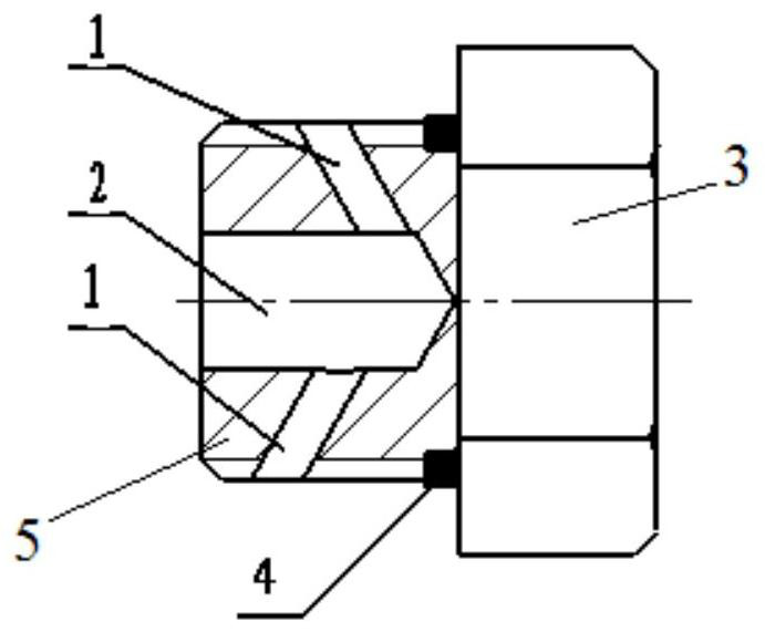
[0033] refer to figure 1 , a screw 5 and head 3 fixedly connected by a splash-proof adjustable plug, the head is an outer hexagonal head; a blind hole 2 is arranged on the screw 5 along the axial direction, and then the screw 5 radially approaches the inner hexagon The position of the end face is respectively processed with two circular oil discharge holes 1 arranged in a staggered arrangement. The included angle, the oil drain hole 1 is set obliquely, and one end of the connection between the oil drain hole 1 and the blind hole 3 is defined as the oil drain hole inlet, and the other end is defined as the oil drain hole outlet, and the distance between the oil outlet and the head 3 is greater than that of the drain hole. The distance between the entrance of the oil hole and the head 3, the axial positions of the two oil discharge holes 1 are at least the distance of the oil discharge hole;

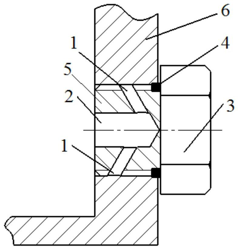
[0034] Plug seal with controllable discharge state such as figure 2 As shown, when ...

Embodiment 2

[0037] refer to Figure 4 The difference between this embodiment and Embodiment 1 is that the screw 5 is provided with 6 oil discharge holes 1 arranged in a staggered arrangement, and the outlet ends of the oil discharge holes 1 located on the same side of the screw 5 are located on the same straight line.

Embodiment 3

[0039] The difference between this embodiment and Embodiment 1 is that several groups of oil discharge holes 1 can be provided on the screw 5 along the circumferential direction, and the outlets of the same group of oil discharge holes 1 are located on the same circumference, so that when the screw is unscrewed, the flow rate can be increased.

[0040] The present invention can realize following function:

[0041] 1. The discharge flow and discharge volume can be controlled: the flow rate can be controlled by adjusting the screw-out length of the plug; when a certain amount of liquid is discharged for a certain period of time or a sufficient amount of liquid, the liquid can be continuously discharged by tightening the plug to block the discharge, so as to realize the precise control of the discharge of the liquid; When a large flow rate is required for complete drainage, the plug can be directly unscrewed completely for quick discharge.

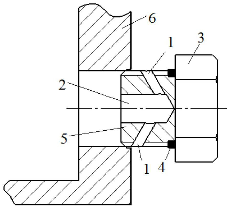
[0042] 2. Prevent splashing: when the...


PUM


Abstract

The invention discloses a splash-proof adjustable plug, which is fixedly connected with a screw rod and a head. The screw rod is provided with a blind hole along the axial direction, and the screw rod is provided with several oil discharge holes along the circumferential direction. The entrance of the oil discharge hole is connected with the blind hole. The holes are connected, the oil discharge hole is arranged obliquely, and the distance between the outlet of the oil discharge hole on the outer peripheral surface of the screw and the head is greater than the distance between the inlet of the oil discharge hole and the head, and the flow rate can be controlled by adjusting the screw-out length of the plug; It also prevents liquid from splashing on the operator during the draining process.

Description

technical field [0001] The invention belongs to the technical field of machinery, and in particular relates to an adjustable anti-splash plug. Background technique [0002] General various liquid tanks, such as the oil tank of the hydraulic station, the vacuum pump oil tank adopts conventional internal (outer) hexagonal screw plugs to block at the discharge port. This type of plug cannot realize the accurate and small discharge operation of the liquid in the liquid storage tank, and there is a problem of splashing at the initial stage of discharge. For example, when it is necessary to sample or discharge a small amount of liquid in the liquid storage tank, all the plugs must be loosened. Due to the high pressure of the liquid at the initial stage of discharge, the discharge flow and speed of the liquid cannot be controlled, and splashing often occurs; in addition, After a sufficient amount of liquid is discharged during sampling, since liquid still flows out from the discha...

Claims


Application Information

Patent Timeline
Patent Type & Authority Patents(China)
IPC IPC(8): F16B35/04F16J15/06
CPCF16B35/04F16J15/06
Inventor 何金梅崔宗凯王海利刘佳张麓娟张玮郭雪丽蔡卿
Owner AECC AVIATION POWER CO LTD
Why Eureka
Try Eureka