
A fan that can purify the air

A technology for purifying air and fans, used in mechanical equipment, machines/engines, liquid fuel engines, etc., to solve problems such as inability to purify air

Active Publication Date: 2020-09-29
安徽悦达环保科技有限公司
View PDF5 Cites 0 Cited by
  • Summary
  • Abstract
  • Description
  • Claims
  • Application Information

AI Technical Summary

Problems solved by technology

Solved the problem that the fan cannot purify the air when it is in use

Method used


Image

  • A fan that can purify the air
  • A fan that can purify the air
  • A fan that can purify the air

Examples


Embodiment Construction

[0022] Below in conjunction with accompanying drawing and embodiment of description, specific embodiment of the present invention is described in further detail:

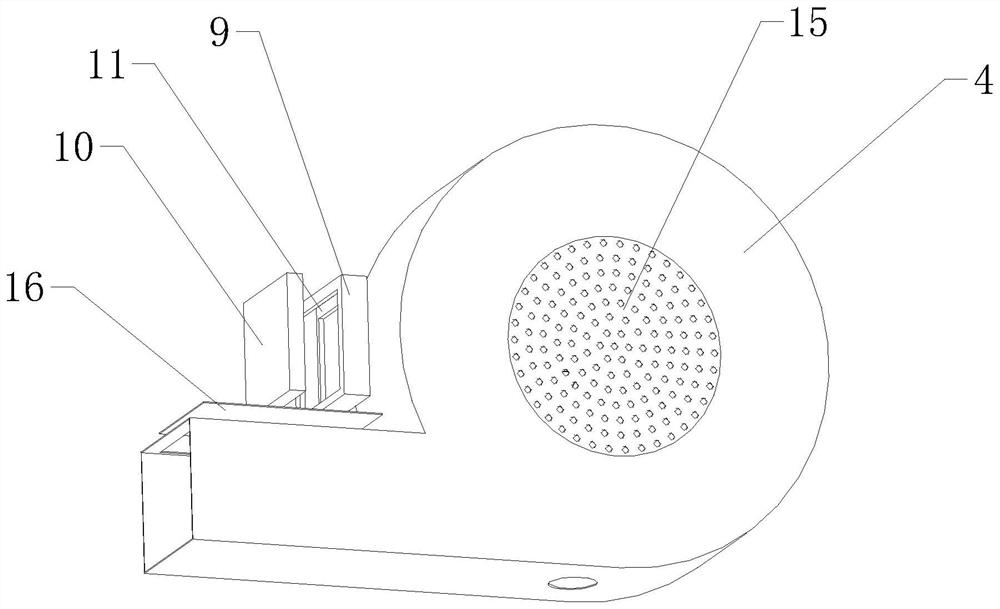
[0023] refer to Figure 1 to Figure 6 A fan capable of purifying air is shown, including a mounting base 1, a blower motor 2, an impeller 3, a blower frame 4 and a purification device. The mounting base 1 is a rectangular block structure, and the mounting base 1 is also provided with The accommodating groove, the blower frame 4 is fixedly installed on the side of the mounting base 1, the bottom of the blasting frame 4 is also provided with an air outlet duct 5, the blower motor 2 is horizontally arranged on the mounting base 1, and the blower motor The output end of 2 is arranged toward the blast frame 4 direction, and impeller 3 includes rotating shaft 6 and a plurality of fan blades 7, and rotating shaft 6 is fixedly connected with the output end of blower motor 2, and fan blades 7 are all arranged on rotating sha...


PUM


Abstract

The invention relates to the field of fan devices, in particular to a fan capable of purifying air. The fan comprises a mounting seat, a blower motor, an impeller, a blower frame and a purifying device. The mounting seat is of a rectangular block structure. The mounting seat is further provided with a holding tank. The blower frame is fixedly mounted on the side of the mounting seat, and the lowerportion of the blower frame is further provided with an air outlet pipe. The blower motor is horizontally disposed on the mounting seat, and the output end of the blower motor is arranged towards theblower frame. The impeller includes a rotating shaft and a plurality of blades, the rotating shaft is fixedly connected with the output end of the blower motor, the blades are all disposed on the rotating shaft, and the impeller is disposed in the blower frame. The purifying device is provided with a spraying device and a plurality of purifying layers. Each purifying layer includes a mounting frame and a filter element, and each mounting frame is disposed in the air outlet pipe and provided with a clamping groove for clamping a filter element. All the filter elements are clamped in the corresponding clamping grooves, a spraying device is arranged in the blasting frame, and the air can be purified during air blowing.

Description

technical field [0001] The invention relates to the field of fan devices, in particular to a fan capable of purifying air. Background technique [0002] The centrifugal fan adopts the latest design and meets the "three modernizations" standard with two rows of large-space cupolas. It is a kind of cupola commonly used in the domestic foundry industry. The coke combustion forms two independent combustion zones. By elongating the overheating zone, the overheating distance of the molten iron and the intense combustion of the bottom coke are increased. The furnace condition is stable, the temperature of the molten iron is high, and the quality of the molten iron is good. According to the air supply temperature, it is divided into two structures: cold air and furnace hot air. Different smelting requirements can be achieved by adopting different temperature air supply. Furnace hot air type utilizes dense rib furnace heat exchanger to heat the physical heat in the furnace gas into ...

Claims


Application Information

Patent Timeline
Patent Type & Authority Patents(China)
IPC IPC(8): F04D25/08F04D25/06F04D29/70
CPCF04D25/0606F04D25/08F04D29/701F04D29/705
Inventor 奚林奚小平
Owner 安徽悦达环保科技有限公司
Learn More