
Presser foot lifting device

A presser foot lifting and presser foot technology, applied in the field of clothing manufacturing equipment, can solve the problems of cumbersome assembly and debugging, high cost, etc.

Active Publication Date: 2018-11-16
BULLMER ELECTROMECHANICAL TECH
View PDF5 Cites 0 Cited by
  • Summary
  • Abstract
  • Description
  • Claims
  • Application Information

AI Technical Summary

Problems solved by technology

[0002] In the existing presser foot lifting device, the presser frame is connected to one drive motor by a set of transmission mechanism, and the presser foot is connected to another drive motor by another set of transmission mechanism. The presser frame and presser foot need to be driven and controlled separately. Assembly and debugging are cumbersome and costly

Method used


Image

  • Presser foot lifting device
  • Presser foot lifting device
  • Presser foot lifting device

Examples


Embodiment Construction

[0030] The following will clearly and completely describe the technical solutions in the embodiments of the present invention with reference to the accompanying drawings in the embodiments of the present invention. Obviously, the described embodiments are only some, not all, embodiments of the present invention. Based on the embodiments of the present invention, all other embodiments obtained by persons of ordinary skill in the art without making creative efforts belong to the protection scope of the present invention.

[0031] The core of the invention is to provide a presser foot lifting device, which simplifies the assembly and debugging process and reduces the cost.

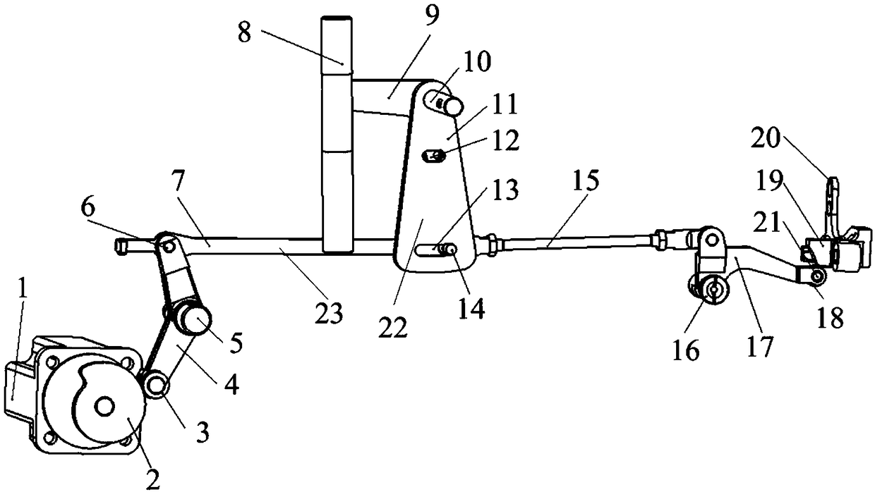
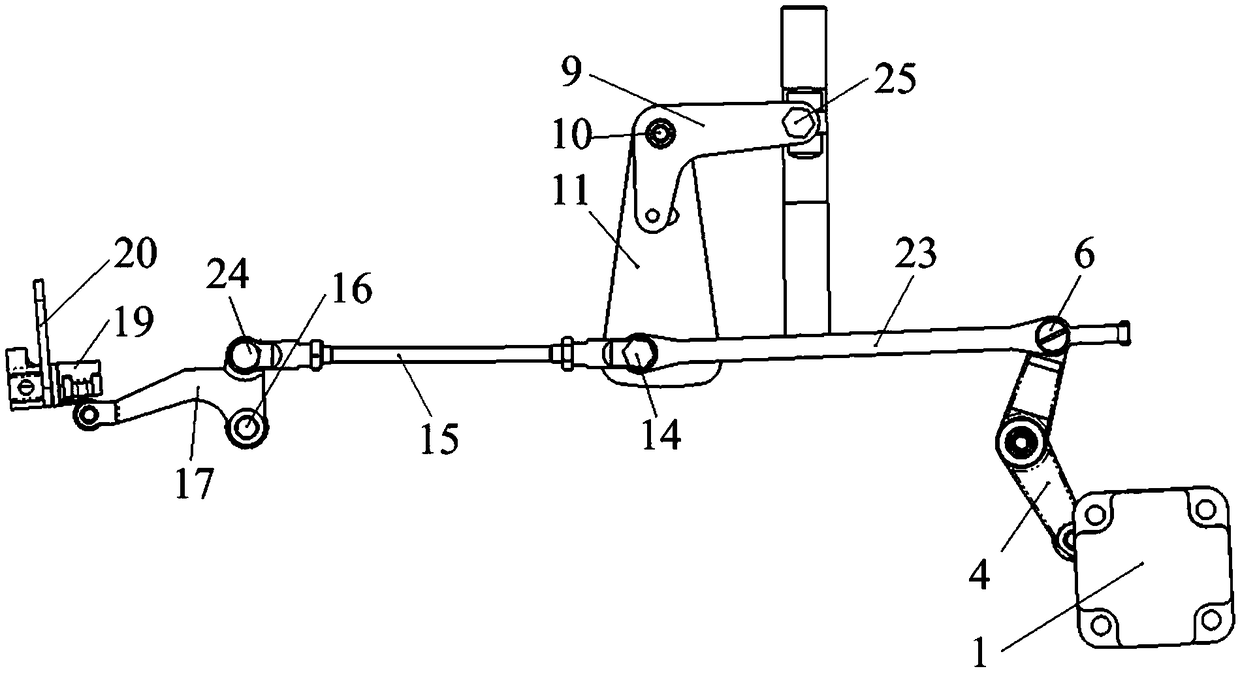
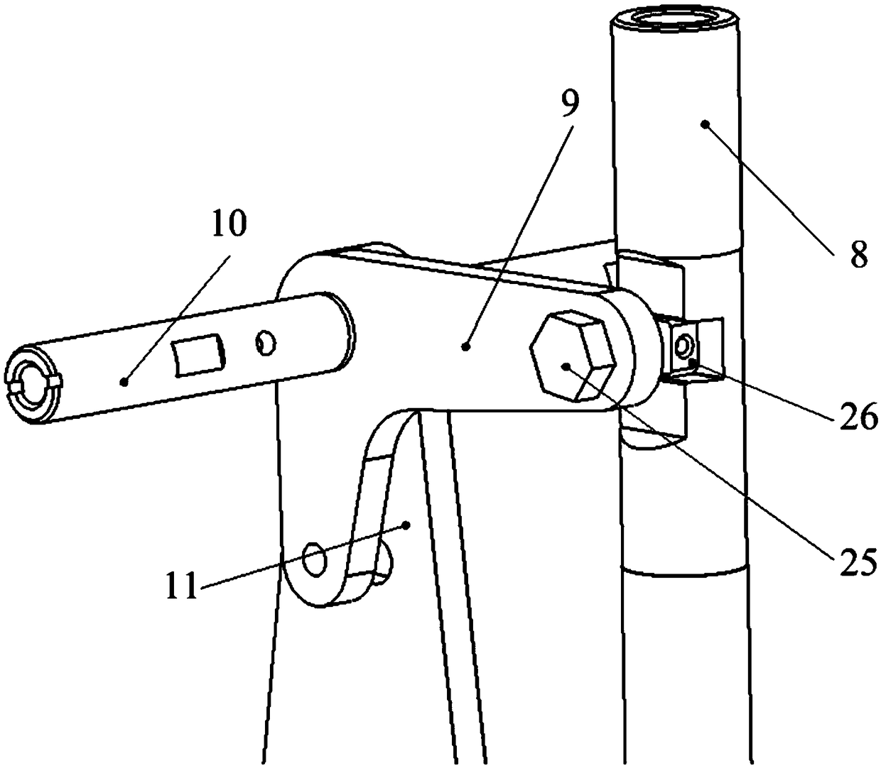
[0032] A specific embodiment of the presser foot lifting device provided by the present invention includes a driving link 7, a driving device 1, a first swing rod 17, a second swing rod 22, a presser foot assembly and a presser frame assembly.

[0033] One point on the first swing link 17 is hinged to the fir...


PUM


Abstract

The invention discloses a presser foot lifting device. A first swing rod of the presser foot lifting device is hinged to a first hinge shaft and a driving connection rod, and a presser foot assembly is provided with a first preset surface and a second preset surface which are used for cooperating with a pushing part of the first swing rod; a second swing rod is hinged to a second hinge shaft, thedriving connection rod is fixedly provided with a push rod for pushing the second swing rod, and a press frame assembly is connected to the second swing rod; the driving device can drive the driving connection rod to reciprocate to drive the first swing rod to swing around the first hinge shaft; the pushing part can drive the presser foot assembly to lift and fall when moving on the first preset surface, and the positions of the second swing rod and the press frame assembly are unchanged; when the pushing part moves on the second preset surface, the position of the presser foot assembly is unchanged, and the push rod drives the second swing rod to swing around the second hinge shaft to drive the press frame assembly to lift and fall. Through the cooperation of the driving device and the second swing rod and through the clutch function of the push rod, the presser foot lifting device can drive press frames and presser feet, the assembly debugging process is simplified, and the cost is reduced.

Description

technical field [0001] The invention relates to the technical field of garment manufacturing equipment, in particular to a presser foot lifting device. Background technique [0002] In the existing presser foot lifting device, the presser frame is connected to one drive motor by a set of transmission mechanism, and the presser foot is connected to another drive motor by another set of transmission mechanism. The presser frame and presser foot need to be driven and controlled separately. Assembly and debugging are cumbersome and costly. [0003] Therefore, how to simplify the assembly and debugging process of the presser foot lifter and reduce the cost is a technical problem that those skilled in the art need to solve. Contents of the invention [0004] In view of this, the object of the present invention is to provide a presser foot lifting device, which simplifies the assembly and debugging process and reduces the cost. [0005] To achieve the above object, the present ...

Claims


Application Information

Patent Timeline
IPC IPC(8): D05B29/02D05B69/02
CPCD05B29/02D05B69/02
Inventor 刘明耀张超波
Owner BULLMER ELECTROMECHANICAL TECH
Learn More