Can cap and spray can

A technology of can lid and lid, applied in the field of spray device, can solve the problems of inconvenient operation, pollution, waste, etc.

Pending Publication Date: 2018-11-16
广东好顺欧迪斯科技股份有限公司
View PDF8 Cites 1 Cited by
  • Summary
  • Abstract
  • Description
  • Claims
  • Application Information

AI Technical Summary

Problems solved by technology

But when it is necessary to kill or repel insects in the gap, due to the small gap entrance, ordinary nozzles need to spray more amount in the gap, and many insecticides will be sprayed outside the gap, causing additional pollution and waste; moreover, when spraying It needs to be pressed all the time to spray, which is inconvenient to operate

Method used


Image

  • Can cap and spray can
  • Can cap and spray can
  • Can cap and spray can

Examples


Embodiment 1

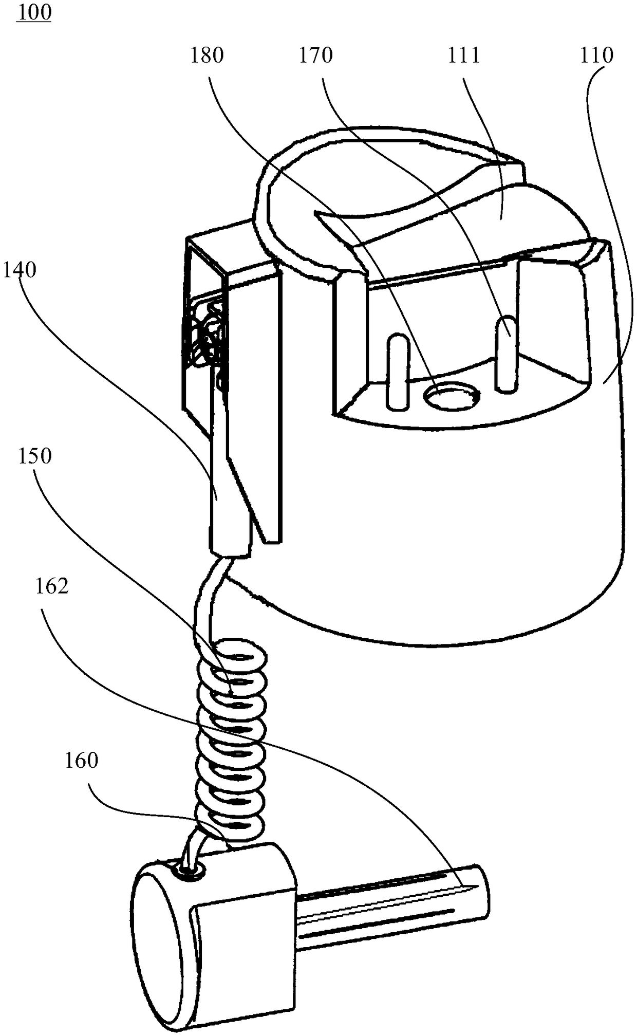
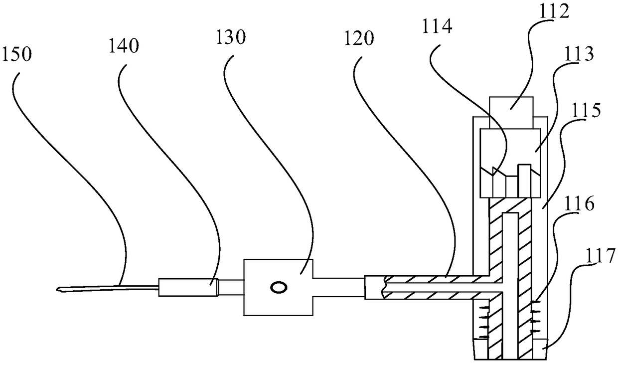
[0031] Please refer to figure 1 , the embodiment of the present invention provides a tank cover 100, including a gland 110, a pressing part 111 is arranged on the gland 110, a push rod 112 is connected under the pressing part 111, and a part of the push rod 112 is arranged in a sleeve 115, and the push rod The end of 112 is provided with a rotating tooth, a chute 113 is arranged below the rotating tooth, a turntable 114 is arranged below the chute 113, and a plurality of convex ribs are evenly distributed on the side wall of the turntable 114, and the number of the chute 113 and the convex ribs are the same and are arranged in cooperation with each other. The rotating gear abuts against the rotating disk 114, and a T-shaped connecting rod 120 is arranged below the rotating disk 114. A wing end of the T-shaped connecting rod 120 is provided with a spring 116, and the sleeve 115 is provided with a limit sleeve 117 at the end of the spring 116. To limit the position of the spring...

Embodiment 2

[0056] The embodiment of the present invention also provides a spray can, comprising a tank body, a nozzle pipe and any one of the above-mentioned tank caps 100, the tank cap 100 is arranged on the tank body, and the T-shaped connecting rod 120 of the tank cap 100 communicates with the nozzle pipe.

[0057] The tank body is a pressure-resistant tank, and there is a preparation in the tank, which is used for spraying to repel or kill insects. The composition and dosage of the preparation are set according to actual needs. Spray cans have different repelling and insecticidal principles depending on the preparation in the tank. For example, when the spray can is used as an aerosol spray can, there are stock solution and propellant in the tank, and the stock solution and propellant are packaged together in the can In vivo, when used, the formulation sprayed in mist form can have an anthelmintic or insecticidal effect.

[0058] In the spray tank provided by the embodiment of the pr...


PUM


Abstract

The invention provides a can cap and a spray can, and belongs to the technical field of spray devices. The can cap comprises a gland which is provided with a pressing part, and the lower side of the pressing part is connected to an ejector rod of which the end is provided with rotating teeth; sliding chutes are formed in the position below the rotating teeth, and a rotating disk is arranged belowthe sliding chutes; the rotating teeth abut against the rotating disk, and a T-shaped communicating rod is arranged below the rotating disk; one wing tip of the T-shaped communicating rod is externally provided with a spring in a sleeving manner, and the end, where a spring is arranged, of a sleeve is connected to a limit sleeve; the pillar end of the T-shaped communicating rod is connected to a connector connected to a liquid outlet part, and the liquid outlet part is connected to a spray cover through a connecting pipe; the spray cover is provided with a spray needle of which the tip extendsout of the spray cover, and the side wall of the spray needle is provided with spray orifices; and the spray orifices communicate with the connecting pipe, the liquid outlet part, the connector and the T-shaped communicating rod so that a through channel is formed. The can cap is simple in structure, and can be inserted into a gap for accurate spraying; surrounding pollution is reduced, and the dosage is decreased; meanwhile, the spraying can be performed continuously after pressing once, and the force for continuous pressing is saved; and the use is convenient and labor-saving.

Description

technical field [0001] The invention relates to the technical field of spraying devices, in particular to a can cover and a spray can. Background technique [0002] In the conventional insecticide tank body, the insecticide aerosol is divergently sprayed through the nozzle to kill or repel insects. But when it is necessary to kill or repel insects in the gap, due to the small gap entrance, ordinary nozzles need to spray more amount in the gap, and many insecticides will be sprayed outside the gap, causing additional pollution and waste; moreover, when spraying It needs to be pressed all the time to spray, which is inconvenient to operate. Contents of the invention [0003] The object of the present invention is to provide a can lid and a spray can, which can continuously spray into a narrow gap after one press. [0004] Embodiments of the present invention are implemented as follows: [0005] In one aspect of the embodiments of the present invention, there is provided a...

Claims


Application Information

Patent Timeline
Patent Type & Authority Applications(China)
IPC IPC(8): B65D83/40B65D83/32B65D83/28
CPCB65D83/28B65D83/32B65D83/40
Inventor 薛笃刘祥海程小蓉
Owner 广东好顺欧迪斯科技股份有限公司
Why Eureka
Try Eureka