High-low edge drive output circuit of finished automobile controller of pure electric automobile
A vehicle controller, pure electric vehicle technology, applied in the direction of circuit devices, circuits or fluid pipelines, emergency protection circuit devices, etc., can solve the problem of affecting the safety of the vehicle, regardless of the fault feedback of the vehicle controller, fault diagnosis control The protection of the output of the device, the reduction of the cost of the hardware circuit of the vehicle controller, etc., to achieve the effect of improving the safety of the vehicle, saving space, and convenient operation
- Summary
- Abstract
- Description
- Claims
- Application Information
AI Technical Summary
Problems solved by technology
Method used
Image
Examples
Embodiment 1
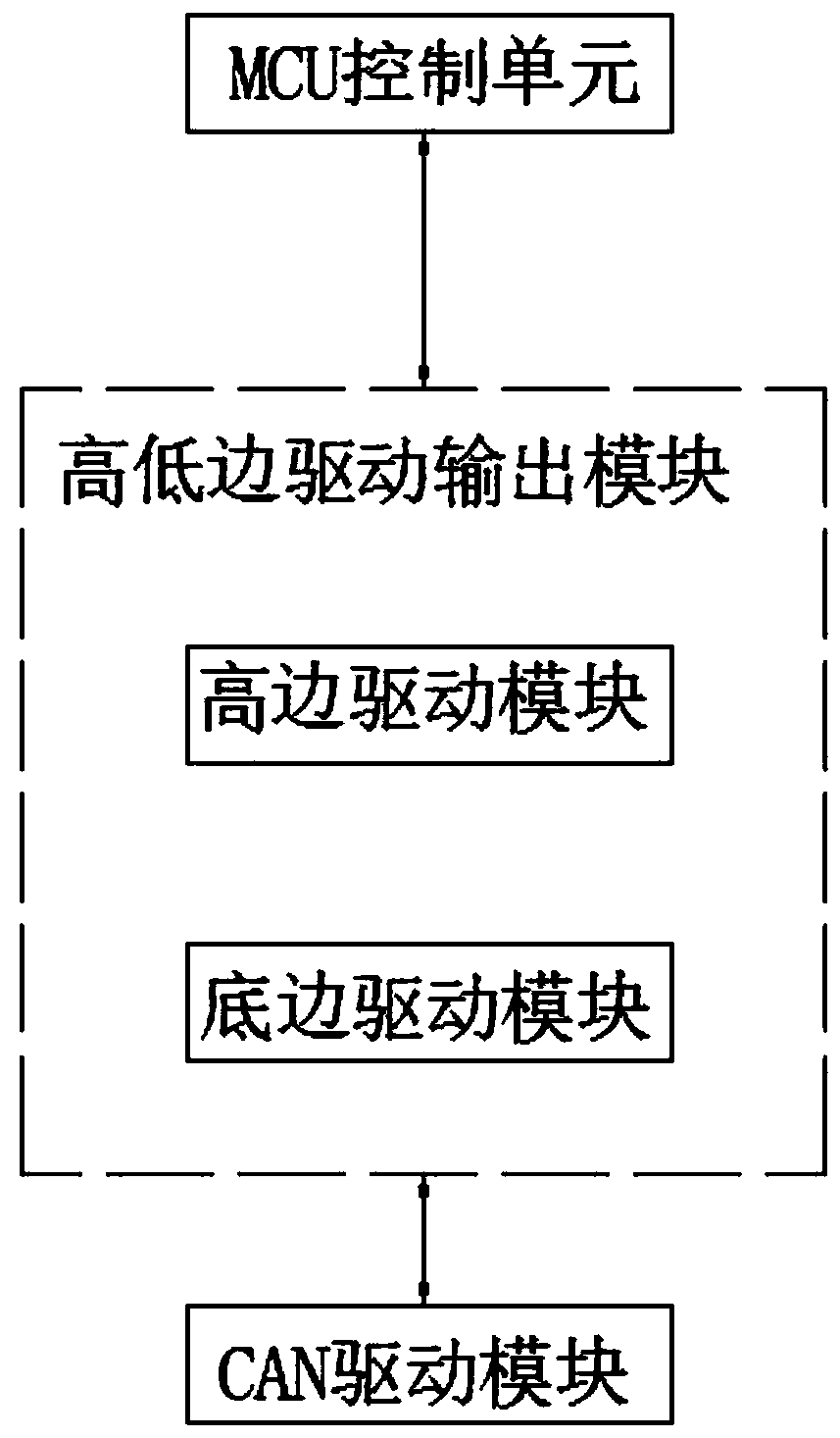
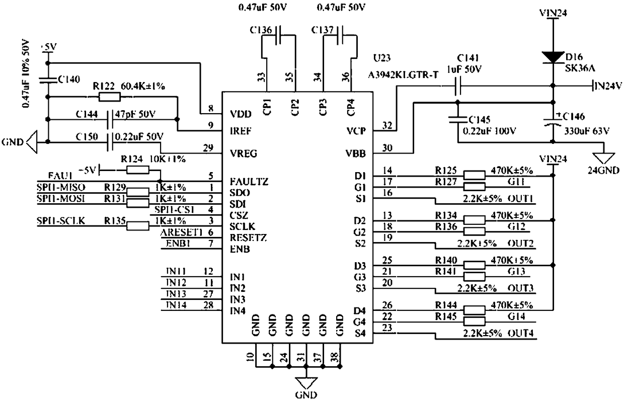
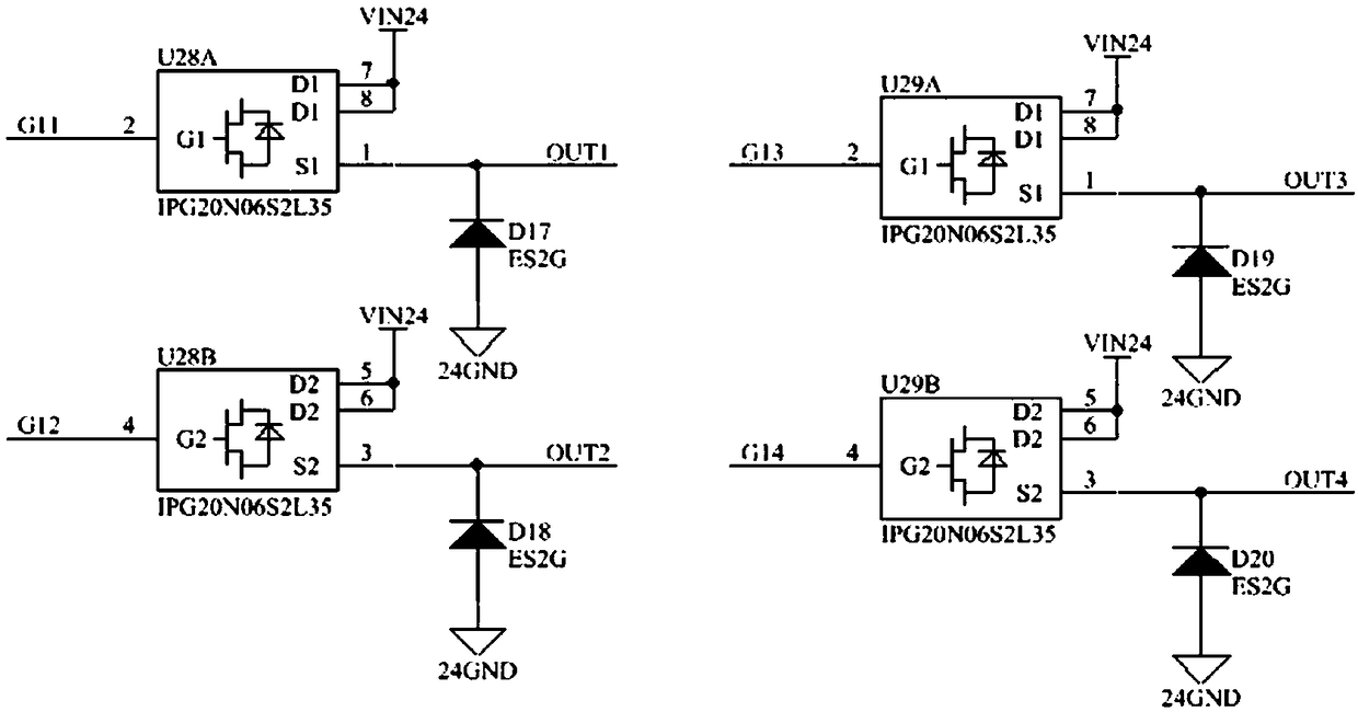
[0019] like figure 2 Shown is the circuit schematic of the high-side drive circuit, as image 3 The high-side output MOSFET circuit is shown, in which the MCU control unit controls the Gx (G1, G2, G3, G4) of the high-side drive circuit to turn on and off a total of 4 gate drive channels through the SPI1 bus, and Gx drives the high-side output MOSFET circuit respectively The IPG20N06S2L35 has a total of 4 MOSFET field effect transistors, which can be connected with inductive and resistive loads as high-side outputs. When the high-side drive circuit detects any fault, it can output to the MCU control unit through an 8-bit Output Fault serial port register connected to the FAULTZ pin of the high-side drive circuit, telling the MCU control unit that there is a fault in the high-side drive output module. Specific faults are divided into system faults and load faults. System faults include: VDD logic power supply undervoltage, VCP charge pump power supply undervoltage, system the...
Embodiment 2
[0021] like Figure 4 Shown is the circuit diagram of the bottom-side drive output module; the MCU control unit controls the 8 low-side output channels in the bottom-side drive output module circuit through the SPI2 bus. Each low-side output channel of the bottom-side drive output module circuit is connected in series with an anti-reverse diode and a freewheeling diode to reduce damage to the bottom-side drive output module circuit due to an external load failure. The bottom edge drive output module circuit has an output voltage clamping function, which can absorb the flyback current of the inductive load. The bottom edge drive output module circuit can diagnose and identify two output fault conditions: (1) overcurrent of OUT1 to OUT6 channels, overcurrent and thermal overload of OUT7 and OUT8 in switching state; (2) open load of all outputs in switching state or short to GND. All output states of the bottom edge driver output module circuit can be read out through the seria...
PUM
 Abstract
Description
Claims
Application Information
 - R&D Engineer
- R&D Manager
- IP Professional
- Industry Leading Data Capabilities
- Powerful AI technology
- Patent DNA Extraction
Browse by: Latest US Patents, China's latest patents, Technical Efficacy Thesaurus, Application Domain, Technology Topic, Popular Technical Reports.
© 2024 PatSnap. All rights reserved.Legal|Privacy policy|Modern Slavery Act Transparency Statement|Sitemap|About US| Contact US: help@patsnap.com


