Automatic feeding device

An automatic material feeding and blank technology, applied in metal processing, etc., can solve the problems of high safety hazards and high labor intensity of manual feeding, and achieve the effect of reducing labor costs, reducing cutting steps, and improving efficiency

Active Publication Date: 2019-11-05
WENZHOU UNIV
View PDF7 Cites 0 Cited by
  • Summary
  • Abstract
  • Description
  • Claims
  • Application Information

AI Technical Summary

Problems solved by technology

[0004] The purpose of the present invention is to provide an automatic feeding device to solve the problems of high labor intensity and potential safety hazards in manual feeding

Method used


Image

  • Automatic feeding device
  • Automatic feeding device
  • Automatic feeding device

Examples


Embodiment Construction

[0020] The following is further described in detail through specific implementation methods:

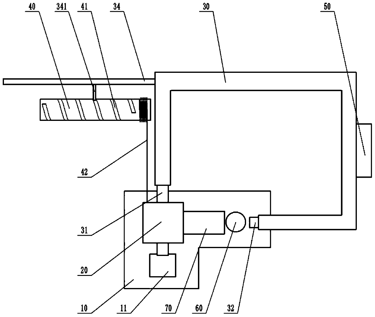
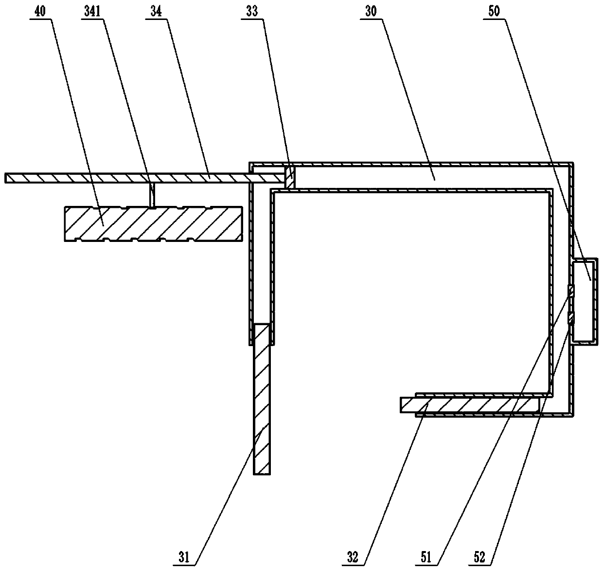
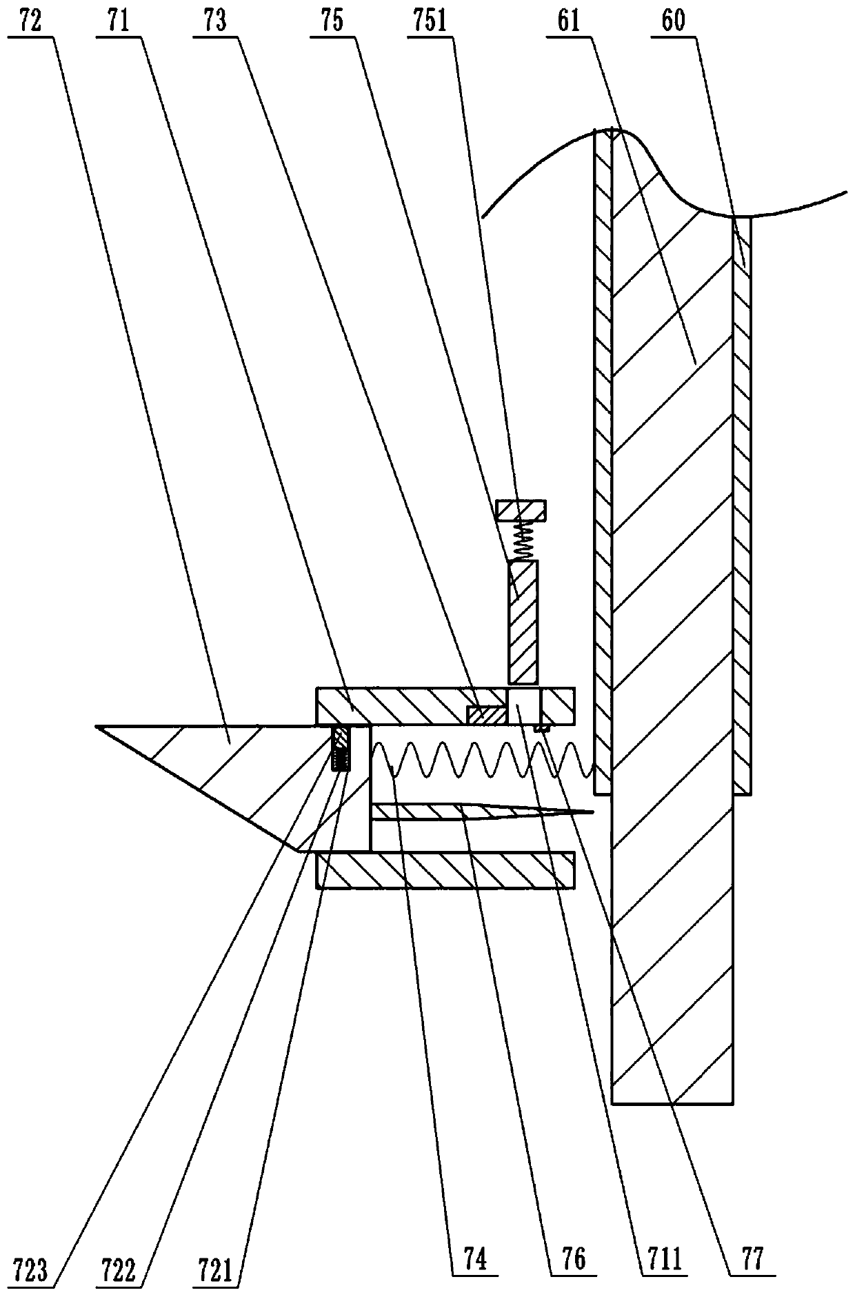
[0021] Instructions attached Figures 1 to 4 The reference signs in include: workbench 10, blanking chute 11, stamping mechanism 20, hydraulic cylinder 21, mounting plate 22, pressing block 23, punch 24, second wedge 25, communication pipe 30, second plunger 31. First plunger 32, piston 33, push rod 34, connecting rod 341, rotating column 40, groove 41, coil 42, liquid storage tank 50, one-way liquid inlet valve 51, one-way liquid discharge valve 52, storage Cylinder 60, blank 61, cutting mechanism 70, sliding sleeve 71, through hole 711, first wedge 72, chute 721, first spring 722, clip 723, electromagnet 73, second spring 74, ejector rod 75 , the third spring 751, the cutting knife 76, the first switch 77.

[0022] Such as figure 1 As shown, the automatic feeding device includes a frame, a transmission unit, a storage unit and a processing unit. The processing unit includes a wo...


PUM


Abstract

The invention belongs to the technical field of machining, and particularly discloses an automatic feeding device. The device comprises a rack, a transmission unit, a storage unit and a machining unit; the machining unit comprises a workbench and a stamping mechanism; the storage unit comprises a cutting mechanism and a storage cylinder; the transmission unit comprises a communicating pipe and a rotating column, a torsional spring is connected between the rotating column and the rack, and hydraulic oil is arranged in the communicating pipe; one side of the communicating pipe is slidably connected with a first plunger, and the other side of the communicating pipe is internally slidably connected with a second plunger; the first plunger and the second plunger are located on two adjacent sides of the stamping mechanism respectively, and the storage unit is located between the first plunger and the stamping mechanism; a piston is slidably connected with the interior of the communicating pipe, and a push rod with one end penetrating through the communicating pipe is fixed to the piston; a spiral groove is formed in the rotating column, and a connecting rod is arranged on the push rod; apulling wire is connected between the rotating column and the stamping mechanism. By the adoption of the device, automatic feeding can be achieved, and the labor intensity of workers is effectively reduced.

Description

technical field [0001] The invention belongs to the technical field of mechanical processing, and in particular relates to an automatic feeding device. Background technique [0002] Upsetting is a forging process that reduces the height of the billet and increases the cross-section. The upsetting process usually includes the following steps: cutting the long billet into a fixed-length segment, then heating the segmental billet, and finally using the punch Stamping is performed on a segmented blank to reduce the height of the blank. When carrying out large-scale upsetting processing on the upsetting machine tool, 23-27 pieces can be processed per minute, and the working stroke of the punch can be adjusted at one time according to the height of the upsetting. [0003] At present, the feeding of upsetting process usually adopts the manual feeding method. When the worker operates, the blank should be pushed into the range of the punch by hand, and the operating frequency must b...

Claims


Application Information

Patent Timeline
Patent Type & Authority Patents(China)
IPC IPC(8): B23Q7/14
CPCB23Q7/14
Inventor 谢晓文
Owner WENZHOU UNIV
Why Eureka
Try Eureka