Cement flue gas denitration method

A flue gas and denitrification technology, applied in the field of cement flue gas denitrification, to achieve the effect of increasing the resistance of flue gas

Inactive Publication Date: 2018-11-16
江苏三创环保科技股份有限公司
View PDF2 Cites 2 Cited by
  • Summary
  • Abstract
  • Description
  • Claims
  • Application Information

AI Technical Summary

Problems solved by technology

[0013] (3) Ammonia escape rate

Method used


Image

  • Cement flue gas denitration method

Examples


Embodiment Construction

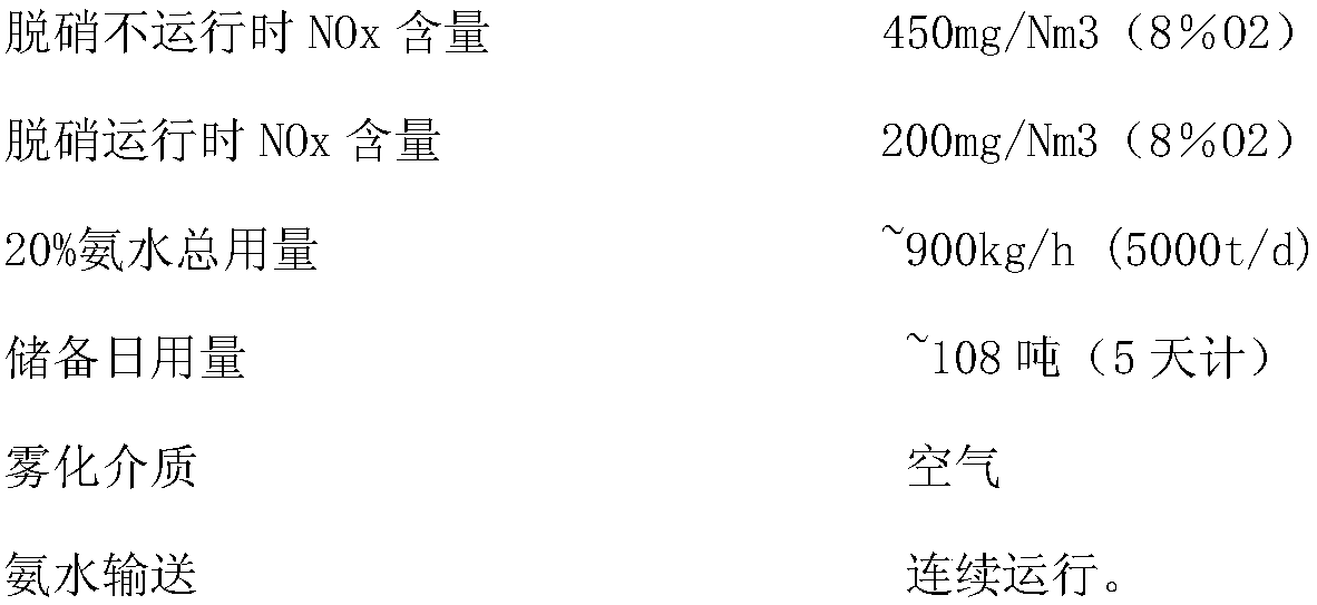
[0028] In the cement flue gas denitrification method of the present invention, the flue gas absorbent is directly sprayed into a suitable temperature zone (850-950° C.) through an atomization injection system, and the atomized flue gas absorbent and NOx (NO, NO2, etc. mixture) Carry out selective non-catalytic reduction reaction to convert NOx into non-polluting N2:

[0029] The flue gas absorbent is 20% mass concentration of ammonia solution, which is transported to the side of the storage tank by an ammonia tank truck, and the discharge pump is turned on to drive the ammonia solution into the storage tank;

[0030] The ammonia solution is diluted through a dilution water pressure control module, and the dilution water pressure control module is composed of two full-flow multi-stage stainless steel centrifugal pumps, a set of duplex filters, a pressure control valve and a pressure / flow meter, etc. ; The total solids in the process water used for reactor dilution should be low...


PUM


Abstract

The invention provides a cement flue gas denitration method which comprises the following steps of directly injecting a flue gas absorbent into a proper temperature region (from 850 DEG C to 950 DEG C) through an atomization injection system, performing selective non-catalytic reduction reaction on the atomized flue gas absorbent and NOx (a mixture of NO, NO2 and the like),and converting the NOx to N2 without pollution, wherein the flue gas absorbent is an ammonia-water solution with the mass concentration being 20 percent; and diluting the ammonia-water solution by a dilution water pressure control module, wherein the dilution water pressure control module mainly comprises two full-flow multi-stage stainless steel centrifugal pump, a group of duplex filters, a pressure control valve and apressure / flow instrument. The cement flue gas denitration method has the following technical effects that (1) in the temperature region (from 800 DEG C to 950 DEG C), a reactant and flue can realizerapid and uniform mixing, and the retention time of the reactant can reach 0.8s or above, so that the condition that the denitration efficiency of 50-70 percent or above is achieved in the kiln SNCR system is ensured.

Description

technical field [0001] The invention relates to a cement flue gas denitrification method, which belongs to the technical field of environmental protection. Background technique [0002] Selective non-catalytic reduction (SNCR) denitrification technology is to spray ammonia (mass concentration 20% to 25%) directly into a suitable temperature area (850 to 950°C) through an atomized injection system, and the atomized ammonia and NOx (NO , NO2 and other mixtures) for selective non-catalytic reduction reaction to convert NOx into non-polluting N2. When the temperature of the reaction zone is too low, the reaction efficiency will decrease; when the temperature of the reaction zone is too high, ammonia will be directly oxidized into N2 and NO. The chemical reactions in the furnace after ammonia spraying are: [0003] 4NO+4NH3+O2→4N2+6H2O [0004] 6NO+4NH3→5N2+6H2O [0005] 6NO2+8NH3→7N2+12H2O [0006] 2NO2+4NH3+O2→3N2+6H2O [0007] In order to improve the efficiency of NOx re...

Claims


Application Information

Patent Timeline
Patent Type & Authority Applications(China)
IPC IPC(8): B01D53/78B01D53/56
CPCB01D53/56B01D53/78B01D2256/10B01D2257/402B01D2257/404B01D2258/0283Y02C20/10
Inventor 郑志根
Owner 江苏三创环保科技股份有限公司
Why Eureka
Try Eureka