LTCC band-pass filter for L band

A band-pass filter and L-band technology, applied in the field of LTCC band-pass filter, can solve the problems of difficult preparation, narrow bandwidth of band-pass filter, complex structure, etc., and achieve high performance

Pending Publication Date: 2018-11-13
GUANGDONG FENGHUA ADVANCED TECH HLDG
View PDF0 Cites 1 Cited by
  • Summary
  • Abstract
  • Description
  • Claims
  • Application Information

AI Technical Summary

Problems solved by technology

[0004] The invention provides an LTCC bandpass filter suitable for L-band, aiming to solve the problems of complex structure, difficult preparation, narrow bandwidth of bandpass filter and the like existing in L-band LTCC bandpass filter.

Method used


Image

  • LTCC band-pass filter for L band

Examples


Embodiment Construction

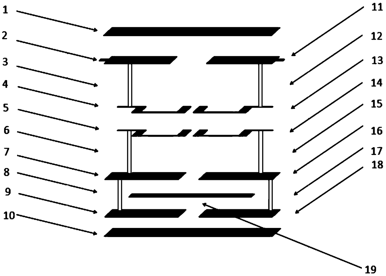
[0008] Such as figure 1 As shown, an LTCC band-pass filter suitable for the L-band includes four resonant units connected in series. The four resonant units are distributed in a square shape in the LTCC band-pass filter. Two resonances in the same line The units form a resonant group, the main resonant group and the secondary resonant group are arranged up and down, and the signal flowing through the band-pass filter sequentially flows through the first resonant unit of the secondary resonant group, the first resonant unit of the main resonant group, and the second resonant unit of the main resonant group. And the second resonant unit of the sub-resonant group. In the present invention, the four resonant units in the filter are arranged in a 4-order cross-coupling structure, that is, the four resonant units are distributed in a square shape, which solves the problem that the current four-stage LTCC bandpass filter in the L-band must be additionally provided with coupling elemen...


PUM


Abstract

The invention discloses an LTCC band-pass filter for an L band. The LTCC band-pass filter comprises four series-connected resonance units. The four resonance units are distributed in the LTCC band-pass filter in a shape like a Chinese character "tian"; each two resonance unit at the same row forms a resonance group; and the main resonance group and the secondary resonance group are arranged up anddown. A signal flowing through the band-pass filter flows through the first resonance unit of the second resonance group, the first resonance unit of the main resonance group, the second resonance unit of the main resonance group and the second resonance unit of the secondary resonance group successively. According to the invention, the four resonance units in the filter are arranged based on a four-order crossed coupling structure and thus distributed in a shape like a Chinese character "tian", so that a problem that an extra coupling element needs to be set for the existing L-band four-level LTCC band-pass filter to realize intersected coupling is solved. With the LTCC band-pass filter, problems of complex structure, difficult preparation, and narrow bandwidth of band-pass filtering ofthe existing L-band LTCC band-pass filter are solved.

Description

Technical field [0001] The present invention relates to a filter, in particular to an LTCC bandpass filter suitable for L-band. Background technique [0002] The filter is a key component of the communication system. It mainly plays the role of frequency selection. It is usually located in the transmitting and receiving components, and the transmitting and receiving components are a key component of the communication system. Therefore, the quality of the filter affects The performance of the entire module and even the entire system, so how to prepare a miniaturized and high-performance filter has become a research object. And LTCC (low temperature co-fired ceramic) new material technology, the metal is printed on the substrate and laminated to form an interconnection, and finally co-fired under low temperature conditions. The printed metal is equivalent to the capacitance, inductance and resistance in the circuit. Such a three-dimensional circuit structure can not only improve s...

Claims


Application Information

Patent Timeline
Patent Type & Authority Applications(China)
IPC IPC(8): H01P1/20
CPCH01P1/20
Inventor 黄明富戴燕城叶文生林鑫黄昆王立东王雄师
Owner GUANGDONG FENGHUA ADVANCED TECH HLDG
Why Eureka
Try Eureka