
Flow guide cover structure of wind power environment-friendly power generation device

A power generation device and a technology of a wind deflector, which is applied to wind power generation, wind power engines, and wind power engines consistent with the wind direction, etc., and can solve the problems of single structure of the wind deflector, concentrated stress at the centrifugal stress point, and low strength of the wind deflector and other problems, to achieve a good effect of collecting wind and blowing sound, and improving the function

Inactive Publication Date: 2018-11-13
程度
View PDF10 Cites 1 Cited by
  • Summary
  • Abstract
  • Description
  • Claims
  • Application Information

AI Technical Summary

Problems solved by technology

[0007] In order to solve the above-mentioned technical problems, the present invention provides a wind deflector structure for an environmentally friendly wind power generation device to solve the above-mentioned problem: the existing wind deflector has a single structure, and its surface is mostly a smooth structure. When the wind blows in, it is not easy to wind Therefore, the effect of wind collection and diversion is poor, and the strength of the purely smooth structure of the guide cover is low. We often find that the elevated wind guide cover is connected to the blade, and there is a phenomenon of fracture. This fracture phenomenon The occurrence is mainly due to the fracture problem caused by the concentrated stress of the centrifugal stress point at the connection part of the blade and the shroud when the blade rotates

Method used


Image

  • Flow guide cover structure of wind power environment-friendly power generation device
  • Flow guide cover structure of wind power environment-friendly power generation device
  • Flow guide cover structure of wind power environment-friendly power generation device

Examples


Embodiment

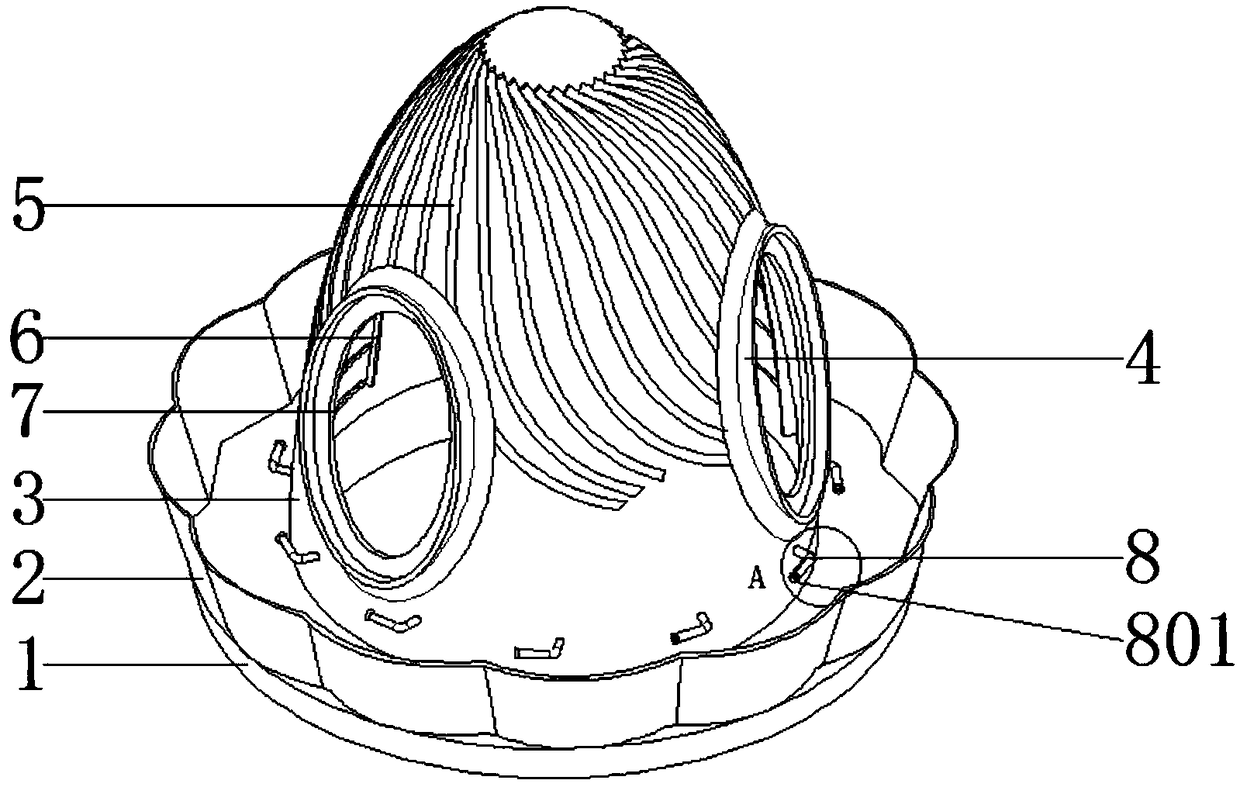
[0034] as attached figure 1 to attach Figure 8 Shown:

[0035] The invention provides a wind deflector structure for an environment-friendly wind power generation device, including a base 1, a functional cover 2, a cover body 3, a blade connection hole 4, a flow guide groove 5, a vertical rib 6, a transverse rib 7, a functional flute 8, and a wind collecting cover 801 and inner end seat 9; a circle of functional cover 2 is installed on the top surface of the base 1, and on the inner side of the functional cover 2, a cover body 3 is installed vertically on the top surface of the base 1, and the inside of the cover body 3 The central position of the cavity and the base 1 realizes opening through; the streamlined surface of the cover body 3 is provided with a plurality of diversion grooves 5, and these diversion grooves 5 are evenly distributed in the vicinity of the blade connection hole 4; A ring of functional flutes 8 is evenly distributed on the outer wall of the bottom si...


PUM


Abstract

The invention provides a flow guide cover structure of a wind power environment-friendly power generation device. The structure comprises an air collection cover and an inner end base, a function cover is arranged on the top face of a base, on the inner side of the function cover, a cover body is vertically arranged on the top face of the base, an inner cavity of the cover body and the central position of the base are in hole forming through connection, multiple flow guide grooves are formed in the streamline form surface of the cover body, and are evenly distributed nearby a blade connectionhole, a ring of function flutes are evenly distributed on the outer wall of the bottom side of the cover body, multiple integral vertical ribs are arranged on the inner cavity of the cover body, a deep groove and an original blade mounting hole are in flow line walking connection, part of blown-in wind enters a mounting blade along with a deep groove, the higher wind amount is provided for the blade, a wind collection function cover of a lotus-like structure is arranged, the blade has the wind collection and rushing functions, and the structural rationality is improved.

Description

technical field [0001] The invention belongs to the technical field of a wind deflector structure and an energy-saving equipment supporting structure, and more specifically relates to a wind deflector structure of an environment-friendly wind power generation device. Background technique [0002] Convert the kinetic energy of the wind into mechanical kinetic energy, and then convert the mechanical energy into electrical kinetic energy. This is wind power generation. The principle of wind power generation is to use wind power to drive the windmill blades to rotate, and then increase the speed of rotation through the speed increaser to promote power generation. According to the current windmill technology, electricity can be generated at a breeze speed (the degree of breeze) of about three meters per second. [0003] The inventor found similar wind deflectors for wind turbines in the process of searching for patents. For example, the application number is: CN201720638101.0 dis...

Claims


Application Information

Patent Timeline
IPC IPC(8): F03D1/06A01M29/16
CPCA01M29/16F03D1/0691Y02E10/72
Inventor 程度
Owner 程度
Learn More