
While-drilling measuring instrument self-locking device and method

A self-locking device and measurement-while-drilling technology, used in earth-moving drilling, wellbore/well components, etc., can solve the problems of increasing the labor intensity of construction personnel, short service life of check valves, and increasing downhole risks. Avoid key-off accidents, protect instruments, and facilitate successful key-setting

Pending Publication Date: 2018-11-13
中石化石油工程技术服务有限公司 +3
View PDF0 Cites 2 Cited by
  • Summary
  • Abstract
  • Description
  • Claims
  • Application Information

AI Technical Summary

Problems solved by technology

The one-way valve (arrow valve) has a short service life. In the eastern part of my country, a well needs to be repaired before it can be used. The usage is very large, which directly increases the production cost.
[0004] 2. Grouting is required when drilling
indirectly increases production costs
[0005] 3. Increased downhole risk
One more joint connected to the downhole drilling tool assembly means one more downhole risk
[0006] 4. Increased labor intensity of construction workers

Method used


Image

  • While-drilling measuring instrument self-locking device and method
  • While-drilling measuring instrument self-locking device and method
  • While-drilling measuring instrument self-locking device and method

Examples


Embodiment 1

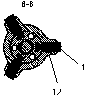
[0027] The present invention includes a self-locking mechanism and an instrument joint, and an instrument joint is provided at the bottom of the self-locking mechanism. 1 is provided with an outer cylinder 2, and the outer cylinder 2 is evenly distributed with three slip grooves 12 in the circumferential direction, and the slips 4 are placed in the slip grooves 12. The inside of the outer cylinder 2 is provided with a bevel body 5, and the bevel body 5 is connected by threads. At the bottom of the fishing head 1, the upper part of the inclined plane body 5 is connected with the lower part of the slips 4, the upper end of the inclined plane body 5 is provided with a locking spring 3, and the lower part of the outer cylinder 2 is provided with an instrument connector, between the inclined plane body 5 and the instrument joint There is a gap between them, the bevel body 5 moves up and down through the locking spring 3, the outer cylinder 2 and the instrument joint are connected by...

Embodiment 2

[0037] The difference from Example 1 is that the outer surface of the slip 4 is provided with gripping teeth 17, which are an alloy layer with extremely high hardness, and the gripping teeth on the surface of the slips eat into the inner wall of the drill tool and are pressed against the inner wall of the drill collar. The formation of locking can avoid the occurrence of key-off accidents of the main body of the measuring instrument and the accident of the instrument falling into the well due to the fracture between the directional joint and the non-magnetic drill collar.

[0038] The instrument joint is connected with the main body of the measuring instrument through the cruise ship 9, and the semicircular clamping flap 10 is stuck to prevent the instrument joint from coming out of the main body of the measuring instrument. The three slips 4 of the cloth protrude outwards and press against the inner wall of the drilling tool. The gripping teeth 17 on the surface of the slips 4...


PUM


Abstract

The invention relates to a while-drilling measuring instrument self-locking device and method. According to the technical scheme, the while-drilling measuring instrument self-locking device comprisesa self-locking mechanism and an instrument connector, an outer cylinder is arranged on the outer side of a salvage head, three slip grooves are evenly distributed on the outer cylinder in the circumferential direction, slips are placed in the slip grooves, a bevel body is arranged in the outer cylinder, and the bevel body is connected to the lower portion of the salvage head in a threaded mode, and the upper portion of the bevel body is connected to the lower portions of the slips. A locking spring is arranged at the upper end of the bevel body, the instrument connector is arranged on the lower portion of the outer cylinder, small springs are installed on a shell of the instrument connector in a sleeving mode, loose pulleys are arranged on the lower portion of the small springs, semicircleclamping clacks are arranged on the lower portion of the loose pulleys, and a ten-core seat assembly is arranged in the shell of the instrument connector. The while-drilling measuring instrument self-locking device and method has the beneficial effects that the while-drilling measuring instrument self-locking device and method can prevent the instrument from bonding-off when drilling down, a one-way valve is no longer used, the cost and trouble are reduced, the instrument is prevented from falling into a well, the instrument is protected, and the safety is improved; a centralizer is equivalent to a durable measuring instrument centralizer assembly; and the instrument is salvageable.

Description

technical field [0001] The invention relates to a measuring instrument while drilling, in particular to a self-locking device and method for the measuring instrument while drilling. Background technique [0002] When domestically using QDT, YST-48X, YST-48R and other measuring instruments for directional well operations, in order to prevent the occurrence of keying-off accidents caused by the drilling fluid in the drilling tool being pushed out of the keyway due to the upward return of the drilling fluid in the drilling tool, currently The common practice is to install a normally closed one-way valve at the lower end of the instrument. The function of this one-way valve is to prevent the drilling fluid in the annular space from entering the drill tool and moving upward when running in, so as to avoid the occurrence of instrument debonding when running in. risk. However, the method of using a one-way valve to prevent the instrument from debonding has at least the following d...

Claims


Application Information

Patent Timeline
Patent Type & Authority Applications(China)
IPC IPC(8): E21B23/01
CPCE21B23/01
Inventor 秦利民李华东冉新兰宁龙马清明邱维清郝雁军蒲文学于克武高伟蒋莉
Owner 中石化石油工程技术服务有限公司
Learn More