A spiral cable support

A spiral and seat plate technology, which is applied in bridge materials, buildings, bridge construction, etc., can solve the problems of complex structure and heavy weight of the upper seat plate and the lower seat plate, and achieve the advantages of small space occupation, weight reduction and simplified structure Effect

Active Publication Date: 2020-07-28
ZHUZHOU TIMES NEW MATERIALS TECH
View PDF5 Cites 0 Cited by
  • Summary
  • Abstract
  • Description
  • Claims
  • Application Information

AI Technical Summary

Problems solved by technology

The cable shock-absorbing support in the prior art has the problems of complex structure and heavy weight of the upper seat plate and the lower seat plate

Method used


Image

  • A spiral cable support
  • A spiral cable support
  • A spiral cable support

Examples


Embodiment 1

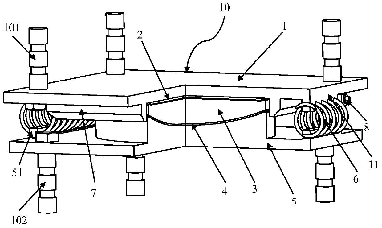
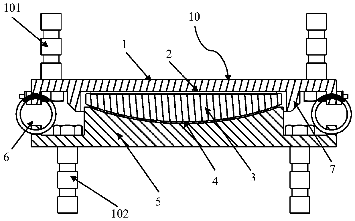
[0031] Such as figure 1 with figure 2 As shown, the spiral cable support 10 of the embodiment of the present invention includes an upper seat plate 1 , an upper slide plate 2 , a spherical crown lining plate 3 , a lower spherical slide plate 4 , a lower seat plate 5 and a spiral cable 6 . The upper slide plate 2 is configured as a plane slide plate arranged between the upper seat plate 1 and the spherical cap liner 3 , and the upper surface and the lower surface of the upper slide plate 2 cooperate with the bottom of the upper seat plate 1 and the top of the spherical crown liner 3 respectively. The lower spherical sliding plate 4 is arranged between the spherical cap liner 3 and the lower seat plate 5 , and the upper surface and the lower surface of the lower spherical sliding plate 4 cooperate with the bottom of the spherical cap liner 3 and the top of the lower seat plate 5 respectively. The spiral stay cables 6 are connected to the upper seat plate 1 and the lower seat p...

Embodiment 2

[0037] Such as Image 6 As shown, the spiral cable support 20 of the embodiment of the present invention includes an upper seat plate 1, an upper slide plate 2′, a spherical crown lining plate 3, a lower spherical slide plate 4, a lower seat plate 5 and a spiral stay cable 6. The upper slide plate 2' is configured as a spherical slide plate arranged between the upper seat plate 1 and the spherical crown lining plate 3, and the upper surface and the lower surface of the upper sliding plate 2 are respectively matched with the bottom of the upper seat plate 1 and the top of the spherical crown lining plate 3. The lower spherical sliding plate 4 is arranged between the spherical cap liner 3 and the lower seat plate 5 , and the upper surface and the lower surface of the lower spherical sliding plate 4 cooperate with the bottom of the spherical cap liner 3 and the top of the lower seat plate 5 respectively. The spiral stay cables 6 are connected to the upper seat plate 1 and the low...


PUM

PropertyMeasurementUnit
Diameteraaaaaaaaaa

Abstract

The invention provides a spiral cable support. The spiral cable support comprises an upper seat plate, an upper sliding plate, a spherical crown liner plate, a lower spherical sliding plate, a lower seat plate and spiral cables. The upper sliding plate is disposed between the upper seat plate and the spherical crown liner plate, and the upper and lower surfaces of the upper sliding plate are separately matched with the bottom of the upper seat plate and the top of the spherical crown liner plate. The lower spherical sliding plate is disposed between the spherical crown liner plate and the lower seat plate, and the upper and lower surfaces of the lower spherical sliding plate are separately matched with the bottom of the spherical crown liner plate and the top of the lower seat plate. The spiral cables are separately connected with the upper seat plate and the lower seat plate, and the spiral cables are horizontally disposed between the upper seat plate and the lower seat plate. Shear resistant baffle blocks are disposed at the bottom of the upper seat plate, and the spiral cables are in contact with the shear resistant baffle blocks in the axial direction. The space occupancy rateis small, the installation is convenient, the structure is simple, and the inspection and replacement are easy, so that the structure can be simplified and the weight can be reduced by the upper seatplate and the lower seat plate of the support.

Description

technical field [0001] The invention belongs to the technical field of bridge damping, and in particular relates to a spiral cable support. Background technique [0002] With the development of the economy, the country has also increased its efforts in infrastructure construction, and bridge engineering has developed rapidly. China is moving from a bridge country to a bridge power. As bridges are pivotal projects on traffic lines, how to prevent the safety of bridge epicenters has become an urgent need. In order to solve the disaster problem in the bridge earthquake, it is the simplest, economical and effective way to set the shock-absorbing and isolating bearing between the superstructure and the substructure of the bridge. The cable shock-absorbing support in the prior art has the problems of complex structure and heavy weight of the upper seat plate and the lower seat plate. Contents of the invention [0003] The technical problem to be solved by the present invention...

Claims


Application Information

Patent Timeline
IPC IPC(8): E01D19/04E01D101/32
CPCE01D19/042E01D19/046E01D2101/32
Inventor 孔令俊陈彦北欧阳柳何俊金杰
Owner ZHUZHOU TIMES NEW MATERIALS TECH
Why Eureka
Try Eureka