A fully automatic cable coiling machine

A cable tie machine, fully automatic technology, applied in the parts of strapping machinery, thin material processing, packaging, etc., can solve the problems of slow wire take-up speed, high labor intensity, inconvenient use in the later stage, etc., to achieve fast wire take-up speed, The effect of low labor intensity and reasonable design

Active Publication Date: 2020-03-10
郑州恒天铜业有限公司
View PDF6 Cites 0 Cited by
  • Summary
  • Abstract
  • Description
  • Claims
  • Application Information

AI Technical Summary

Problems solved by technology

[0002] As we all know, after using the cable, it needs to be closed to facilitate later storage and use. By closing the cable, it can avoid cable knotting and other phenomena, which can not only create convenience for later use but also prolong the service life of the cable; at present, Most of the cable winding is done manually, which has the disadvantages of slow winding speed, high labor intensity, time-consuming and labor-intensive, etc. The closing of some cables is that the cable is directly connected to the cable reel, and the cable is realized by the rotation of the motor in the cable reel. Fast closing, but the cable reel is relatively heavy, and the cable reel needs to be moved to the site together when using it, and because the motor rotates at a high speed and there is no combing device when the wire is taken up later, it is easy to cause the tangled cable to be directly coiled in the cable reel. It not only affects the service life of the cable, but also makes it inconvenient to use later

Method used


Image

  • A fully automatic cable coiling machine
  • A fully automatic cable coiling machine
  • A fully automatic cable coiling machine

Examples


Embodiment 1

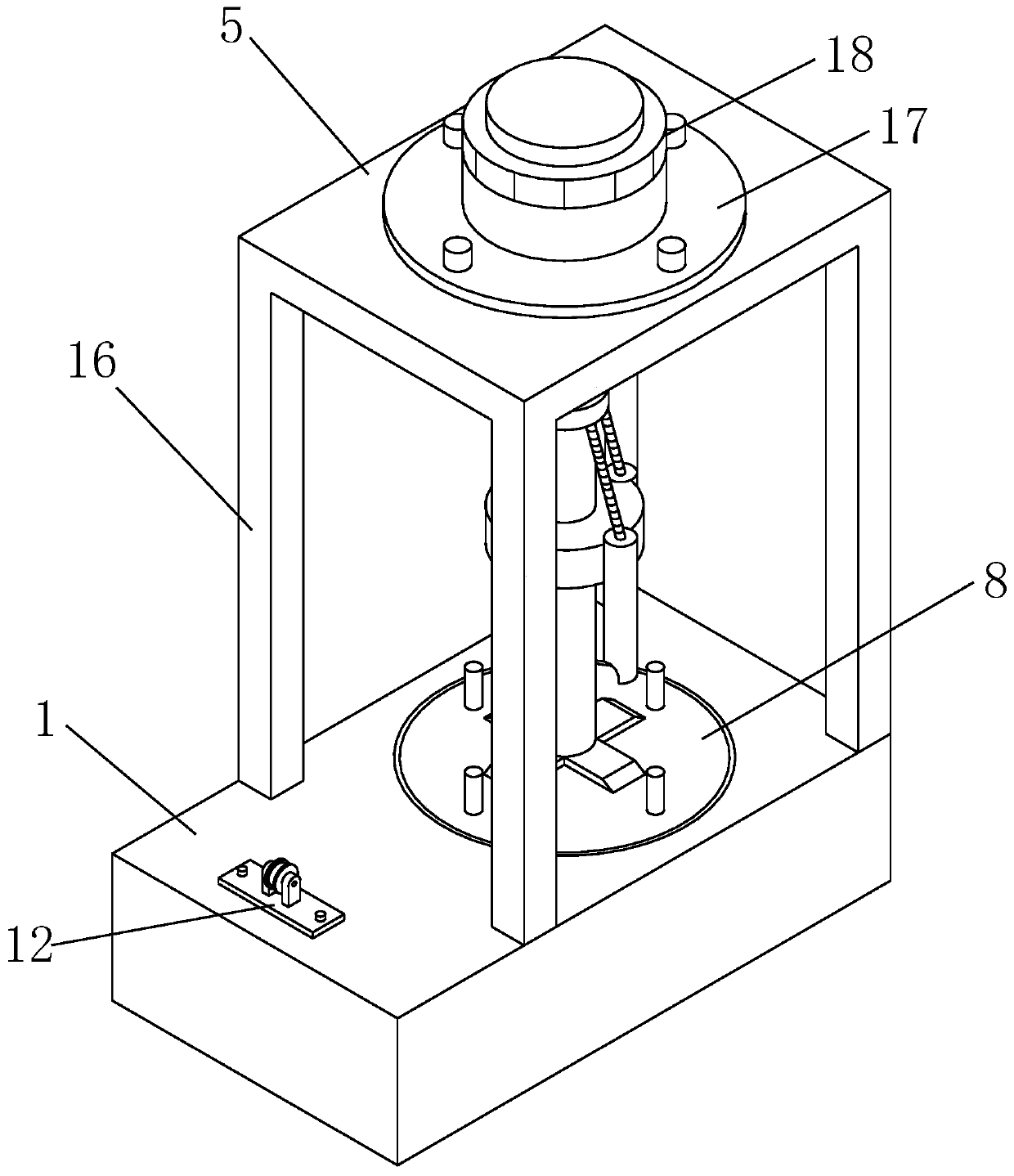
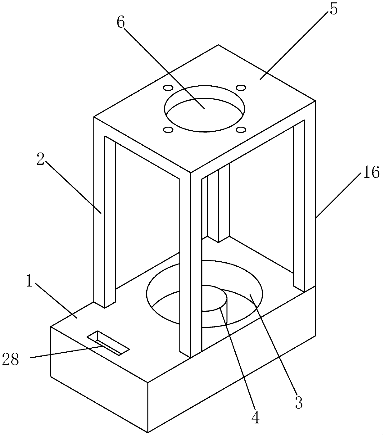
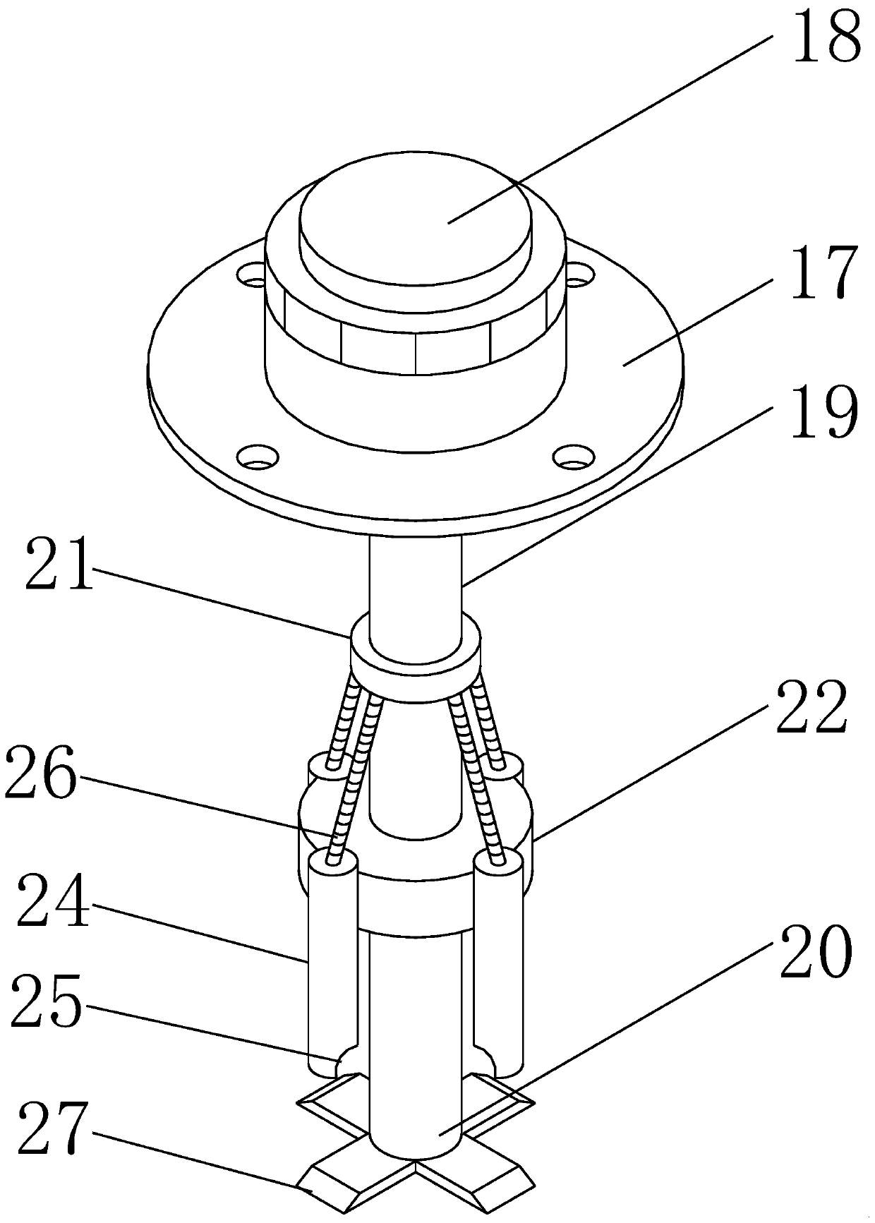
[0021] A fully automatic cable coiling machine, comprising a device base 1, the top of the device base 1 is provided with a combing device and a manipulator fixing frame 2 arranged on one side of the combing device, and the inside of the manipulator fixing frame 2 corresponds to The upper surface of the device base 1 is provided with a first installation hole 3, the center of the first installation hole 3 is provided with a rotating shaft 4, and a second installation hole 3 is provided on the fixing plate 5 of the manipulator holder 2 corresponding to the top of the first installation hole 3. Mounting hole 6, the second mounting hole 6 is equipped with a manipulator unit; the inside of the first mounting hole 3 is connected to the turntable device 8 through the bearing 7, and the bottom of the turntable device 8 is provided with a rotating shaft that is compatible with the rotating shaft 4 Hole 9, the middle position of the upper surface of the turntable device 8 is provided wi...

Embodiment 2

[0023]A fully automatic cable coiling machine, comprising a device base 1, the top of the device base 1 is provided with a combing device and a manipulator fixing frame 2 arranged on one side of the combing device, and the inside of the manipulator fixing frame 2 corresponds to The upper surface of the device base 1 is provided with a first installation hole 3, the center of the first installation hole 3 is provided with a rotating shaft 4, and a second installation hole 3 is provided on the fixing plate 5 of the manipulator holder 2 corresponding to the top of the first installation hole 3. Mounting hole 6, the second mounting hole 6 is equipped with a manipulator unit; the inside of the first mounting hole 3 is connected to the turntable device 8 through the bearing 7, and the bottom of the turntable device 8 is provided with a rotating shaft that is compatible with the rotating shaft 4 Hole 9, the middle position of the upper surface of the turntable device 8 is provided wit...

Embodiment 3

[0025] A fully automatic cable coiling machine, comprising a device base 1, the top of the device base 1 is provided with a combing device and a manipulator fixing frame 2 arranged on one side of the combing device, and the inside of the manipulator fixing frame 2 corresponds to The upper surface of the device base 1 is provided with a first installation hole 3, the center of the first installation hole 3 is provided with a rotating shaft 4, and a second installation hole 3 is provided on the fixing plate 5 of the manipulator holder 2 corresponding to the top of the first installation hole 3. Mounting hole 6, the second mounting hole 6 is equipped with a manipulator unit; the inside of the first mounting hole 3 is connected to the turntable device 8 through the bearing 7, and the bottom of the turntable device 8 is provided with a rotating shaft that is compatible with the rotating shaft 4 Hole 9, the middle position of the upper surface of the turntable device 8 is provided wi...


PUM


Abstract

The invention belongs to a full-automatic cable coiling binding machine. The full-automatic cable coiling binding machine comprises a device base, wherein the top of the device base is provided with acombing device and a mechanical arm fixing frame arranged on one side of the combing device, a first mounting hole is formed in the upper surface of the device base corresponding to the inside of themechanical arm fixing frame, a rotating shaft is arranged at the center of the first mounting hole, a second mounting hole is formed in the fixing plate of the mechanical arm fixing frame corresponding to the top of the first mounting hole, and a mechanical arm unit is arranged in the second mounting hole; and the interior of the first mounting hole is connected with a rotary disc device througha bearing, a rotating shaft hole matched with the rotating shaft is formed in the bottom of the rotating disc device, a groove matched with a grabbing disc is formed in the middle of the upper surfaceof the rotating disc device, and a plurality of winding rods are arranged on the edge of the upper surface of the rotating disc device. The full-automatic cable coiling binding machine has the advantages of being simple in structure, reasonable in design, high in wire coiling speed, and low in labor intensity, and can comb the coiled cable.

Description

technical field [0001] The invention belongs to the technical field of cable winding, and in particular relates to a fully automatic cable winding machine. Background technique [0002] As we all know, after using the cable, it needs to be closed to facilitate later storage and use. By closing the cable, it can avoid cable knotting and other phenomena, which can not only create convenience for later use but also prolong the service life of the cable; at present, Most of the cable winding is done manually, which has the disadvantages of slow winding speed, high labor intensity, time-consuming and labor-intensive, etc. The closing of some cables is that the cable is directly connected to the cable reel, and the cable is realized by the rotation of the motor in the cable reel. Fast closing, but the cable reel is relatively heavy, and the cable reel needs to be moved to the site together when using it, and because the motor rotates at a high speed and there is no combing device ...

Claims


Application Information

Patent Timeline
Patent Type & Authority Patents(China)
IPC IPC(8): B65H57/14B65H54/44B65H67/04B65B13/18B65B63/04
CPCB65B13/18B65B63/04B65H54/44B65H57/14B65H67/0411B65H2701/34B65H2801/81
Inventor 刘永勋陈芳王红霞杨保海马秉馨毋加加胡洪洋
Owner 郑州恒天铜业有限公司
Why Eureka
Try Eureka