Adjustable supporting seat for carrying intelligent furniture
A smart home, adjustable technology, applied in the directions of transportation and packaging, manual conveying devices, etc., can solve the problems of troublesome handling workers, inconvenient furniture handling, heavy smart furniture, etc. Effects of Sex and Adjustability
- Summary
- Abstract
- Description
- Claims
- Application Information
AI Technical Summary
Problems solved by technology
Method used
Image
Examples
Embodiment 1
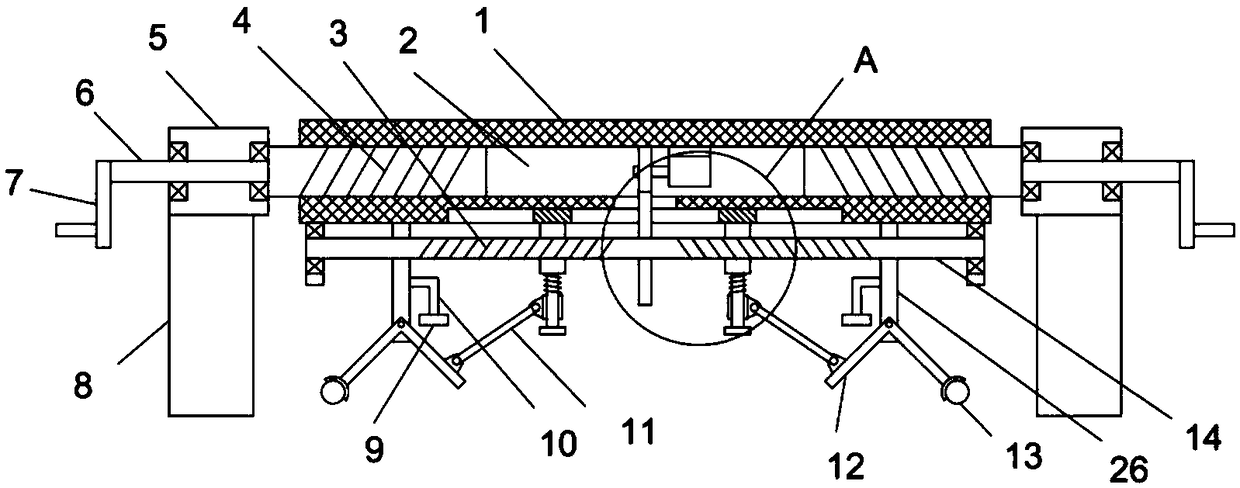
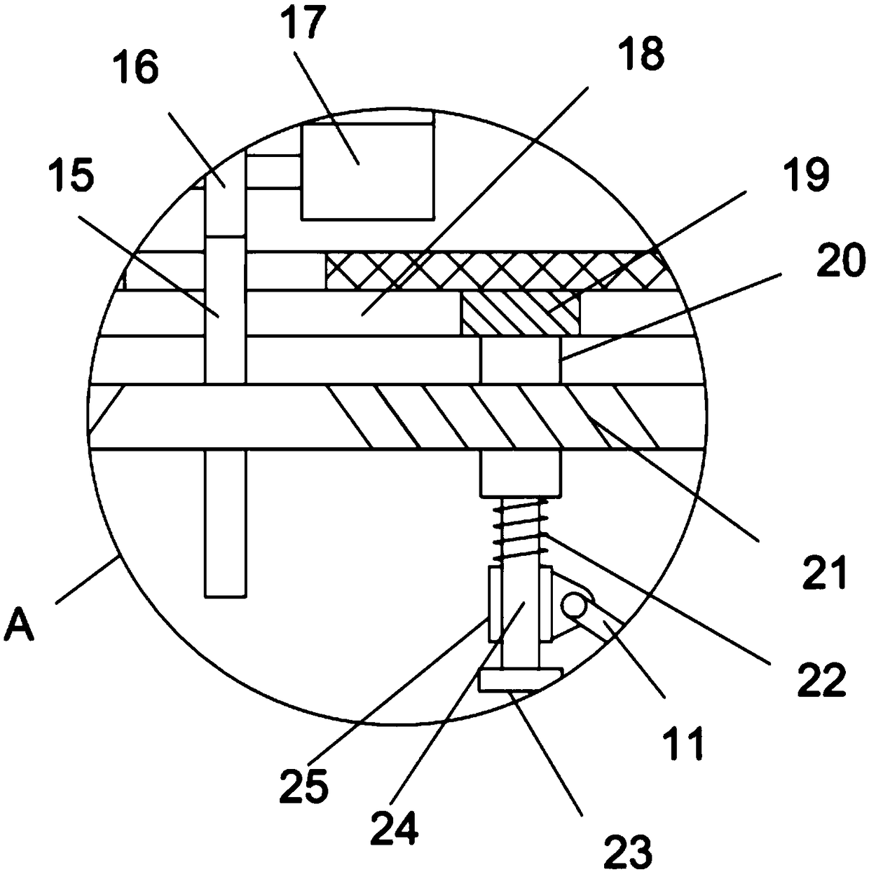
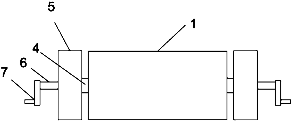
[0022] see Figure 1-4 , an adjustable support seat for smart home transportation, including a support platform 1 and a movable frame 5 connected to the adjustment shaft 4 through the adjustment shaft 4, the support platform 1 is provided with a cavity 2, and the bottom surface of the support platform 1 is vertically fixed A support leg 8 is installed, and the support leg 8 is a plate-like structure; the adjustment shaft 4 is screwed into the support table 1, and the end of the adjustment shaft 4 away from the support table 1 is fixedly installed with a rotating shaft 6 that runs through the movable frame 5; The bottom of the support table 1 is provided with an adjustable threaded rod 14 in a rotating manner, and the surface of the left half and right half of the adjusted threaded rod 14 is respectively tapped with a first thread 3 and a second thread 21, and the first thread 3 and the second thread 21 The direction of rotation of the thread is opposite, and the adjusting thre...
Embodiment 2
[0026] On the basis of Embodiment 1, in addition, a forward and reverse motor 17 is fixedly installed in the cavity 2, and the output shaft of the forward and reverse motor 17 is coaxially fixed with a driving gear 16, and the middle part of the adjusting threaded rod 14 is sleeved and fixed. A driven gear 15 meshingly connected with the driving gear 16 is installed. When the smart furniture placed on the support platform 1 is moved and carried by the device, the forward and reverse motor 17 is started, and the forward and reverse motor 17 drives the driving gear 16 to rotate. The driving gear 16 drives the adjusting threaded rod 14 to rotate through the driven gear 15 meshed with it, the first thread 3 and the second thread 21 on the adjusting threaded rod 14 have opposite helical directions, the reversing motor 17 rotates forward, and the adjusting thread Rod 14 drives threaded sleeve 20 to move toward each other, and threaded sleeve 20 drives limit shaft 24 to move toward ea...
Embodiment 3
[0028] On the basis of Embodiment 2, in addition, the lower bottom surface of the support table 1 is provided with a guide groove 18 transversely, and the upper end of the threaded sleeve 20 is fixed and slidably installed with a guide slider 19 embedded in the guide groove 18; A damping spring 22 is provided, the upper end of the damping spring 22 is fixed on the bottom surface of the threaded sleeve 20, the lower end of the damping spring 22 is fixed on the upper surface of the moving sleeve 25, and the lower end of the limit shaft 24 is fixedly installed with a diameter larger than the sliding sleeve 25. In the process of moving the threaded sleeve 20, the guide slider 19 slides along the guide groove 18 to play a role of limiting and guiding the movement of the threaded sleeve 20, while the sliding sleeve 25 moves along the limit The bit axis 24 moves up and down, and the shock absorbing spring 22 deforms, elongates and compresses, which plays an elastic damping effect on t...
PUM
 Abstract
Description
Claims
Application Information
 - R&D Engineer
- R&D Manager
- IP Professional
- Industry Leading Data Capabilities
- Powerful AI technology
- Patent DNA Extraction
Browse by: Latest US Patents, China's latest patents, Technical Efficacy Thesaurus, Application Domain, Technology Topic, Popular Technical Reports.
© 2024 PatSnap. All rights reserved.Legal|Privacy policy|Modern Slavery Act Transparency Statement|Sitemap|About US| Contact US: help@patsnap.com


