
Triple-fan assembly line

An assembly line and fan technology, applied in the field of triple fan assembly line, can solve the problems of low degree of automation, low assembly accuracy and fixation, low assembly efficiency, etc., and achieve the effect of increasing flexibility and stable and efficient assembly work

Inactive Publication Date: 2018-11-13
俞斌
View PDF8 Cites 2 Cited by
  • Summary
  • Abstract
  • Description
  • Claims
  • Application Information

AI Technical Summary

Problems solved by technology

The assembly process of this fan is simple, the degree of automation is low, and the assembly accuracy and fixation are not high.
The utility model with the application number 201620520782.6 discloses an automatic fan assembly production line, which includes a sequentially connected feeding unit, a control assembly, a first assembly unit, a second assembly unit, and a final assembly unit; the feeding unit includes a feeding manipulator and Fan frame feeding platform; the control assembly includes the first belt conveyor line, man-machine interface and electric control box; the first assembly unit includes the second belt conveyor line, shrapnel loading manipulator, buckle ring loading manipulator, gasket loading Manipulator, bearing manipulator, oiling manipulator, shrapnel feeding unit, buckle and gasket feeding unit, bearing feeding unit and vision alignment unit; the second assembly unit includes a third belt conveyor line, a motor pre-pressing station and Motor press-fitting station; the assembly unit includes a fan feeding platform, assembly and handling robot, quick-change fixture platform, and packing platform; although it has a certain degree of automation, the assembly efficiency is too low, and it is difficult for the stability of the assembly Insufficient sex testing

Method used


Image

  • Triple-fan assembly line
  • Triple-fan assembly line
  • Triple-fan assembly line

Examples


Embodiment Construction

[0043] The following will clearly and completely describe the technical solutions in the embodiments of the present invention with reference to the accompanying drawings in the embodiments of the present invention. Obviously, the described embodiments are only some, not all, embodiments of the present invention. Based on the embodiments of the present invention, all other embodiments obtained by persons of ordinary skill in the art without making creative efforts belong to the protection scope of the present invention.

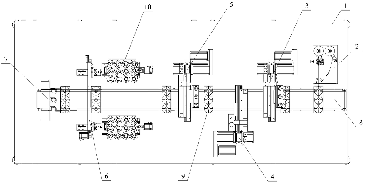
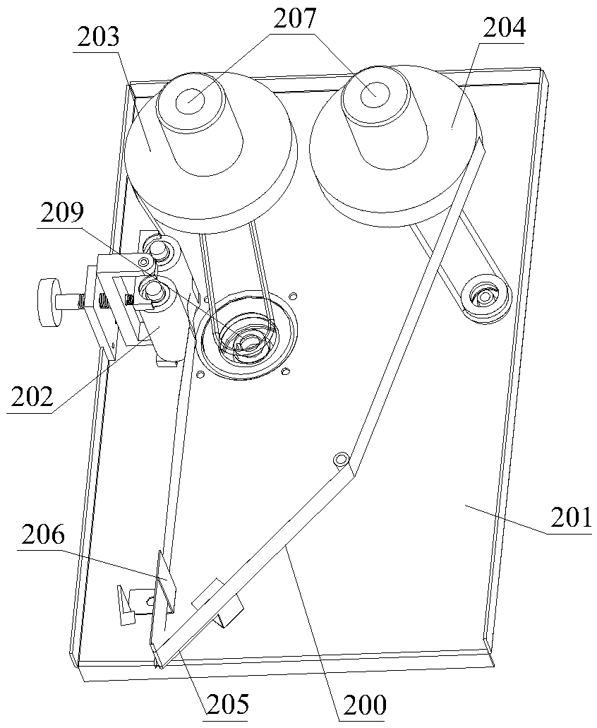
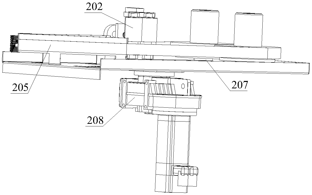
[0044] Such as Figure 1-11 As shown, a triple fan assembly line includes a frame 1, a labeling unit 2 arranged on the frame 1, a first glue injection unit 3, a video detection unit 4, a second glue injection unit 5, an assembly unit 6, Compression unit 7 and material unit 10, described labeling unit 2, first glue injection unit 3, video detection unit 4, second glue injection unit 5, assembly unit 6 and compression unit 7 are arranged successively by conveyor...


PUM


Abstract

The invention discloses a triple-fan assembly line. The triple-fan assembly line comprises a rack, a labeling unit, a first glue injection unit, a video detection unit, a second glue injection unit, an assembly unit, a tightly-pressing unit and material units, wherein the labeling unit, the first glue injection unit, the video detection unit, the second glue injection unit, the assembly unit, thetightly-pressing unit and the material units are arranged in the rack. The labeling unit, the first glue injection unit, the video detection unit, the second glue injection unit, the assembly unit andthe tightly-pressing unit are sequentially arranged through a conveying belt. The labeling unit is arranged at the input end of the conveying belt. The tightly-pressing unit is arranged at the outputend of the conveying belt. The first glue injection unit is arranged between the labeling unit and the video detection unit. The second glue injection unit is arranged between the video detection unit and the assembly unit. The triple-fan assembly line is high in assembly efficiency, manufacturing efficiency is greatly improved, and the production cost is lowered.

Description

technical field [0001] The invention relates to the field of mechanical automation, and more specifically, relates to a triple fan assembly line. Background technique [0002] A fan is a commonly used heat dissipation device on a heating device. For a heating device with a large heat dissipation requirement, it is generally necessary to install multiple fans at the same time to achieve a cooling effect. The fan is generally installed on the casing with screws and nuts, and then the casing is installed on the device. In order to ensure the normal operation of the fan, a fan cover needs to be installed on the fan to protect the fan. How to quickly and firmly assemble the fan, the fan cover and the housing through screws and nuts affects the efficiency of manufacturing and is also a problem that relevant technicians attach great importance to. [0003] In the prior art, the operator clamps the nut with needle-nose pliers in one hand, and locks the screw with an electric screwd...

Claims


Application Information

Patent Timeline
IPC IPC(8): B23P21/00B05C5/02B05C11/10
CPCB05C5/02B05C11/10B23P21/004
Inventor 俞斌
Owner 俞斌
Learn More