Industrial pressure vessel convenient to move

A pressure vessel and industrial technology, applied in the field of industrial pressure vessels that are easy to move, can solve the problems of lack of anti-skid protection at the base fixed place, reducing the use effect of the pressure vessel, and difficult to move freely, so as to improve the placement stability and enhance the flexibility of use. , the effect of convenient movement

Inactive Publication Date: 2018-11-09
张凯帆
View PDF0 Cites 0 Cited by
  • Summary
  • Abstract
  • Description
  • Claims
  • Application Information

AI Technical Summary

Problems solved by technology

[0003] However, existing industrial pressure vessels have some deficiencies during use. Their structures are cumbersome, making it difficult to move freely. At the same time, there is also a lack of anti-slip protection measures for the fixed base, which reduces the use effect of pressure vessels.

Method used


Image

  • Industrial pressure vessel convenient to move
  • Industrial pressure vessel convenient to move
  • Industrial pressure vessel convenient to move

Examples


Embodiment 1

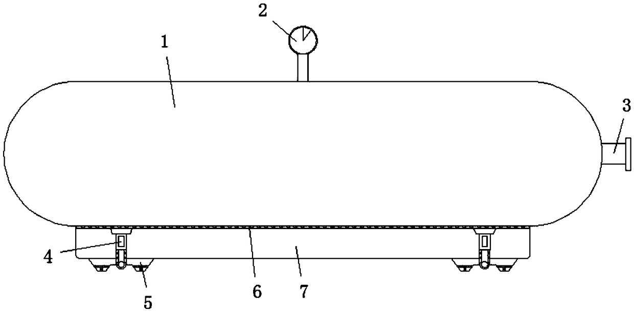
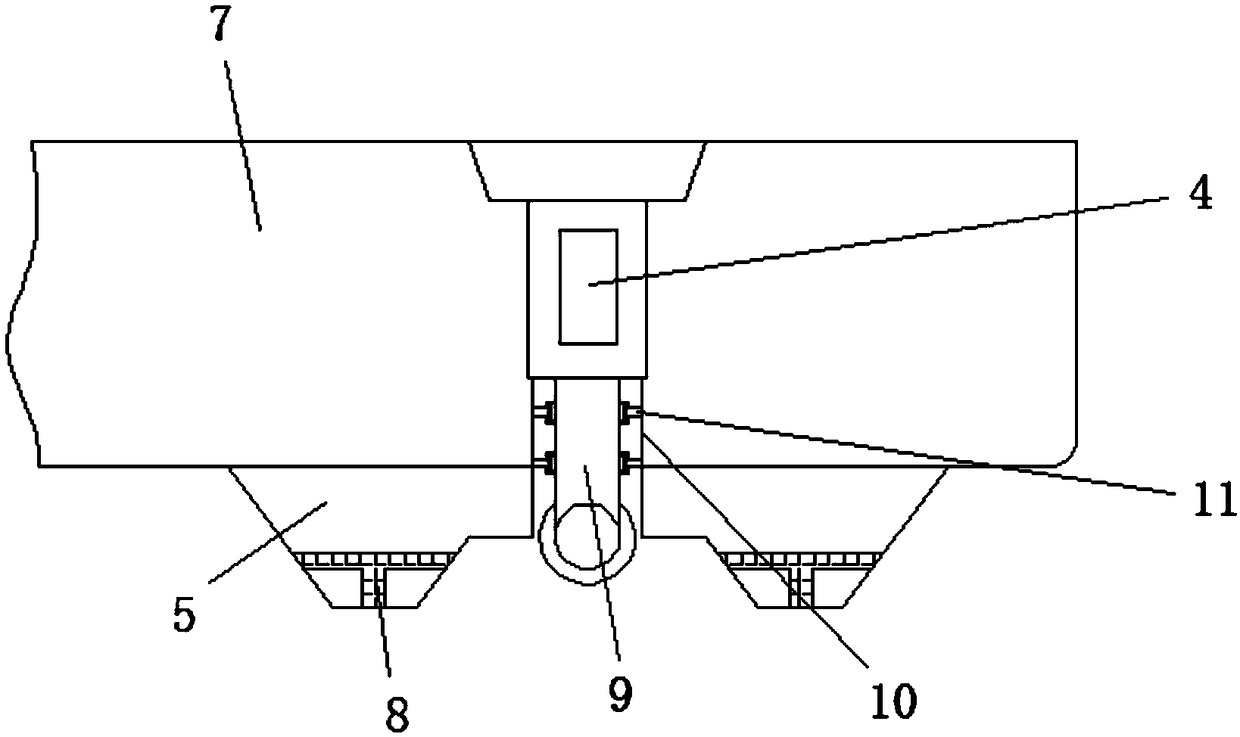
[0027] Example one, reference Figure 1-4 , An industrial pressure vessel that is easy to move, comprising a tank body 1 and a base 7. The upper surface of the base 7 is welded with a tank body 1, and a barometer 2 is set at the center of the upper surface of the tank body 1. The wall is welded with a gas pipeline 3, the bottom of the base 7 is welded with spacer blocks 5 symmetrically on both sides, the top of the inner surface wall of the base 7 is bolted with a driving cylinder 4, and the bottom of the driving cylinder 4 is connected with a connecting rod 9 through a telescopic rod. The bottom of the connecting rod 9 is movably connected with universal wheels 13, the outer walls of the connecting rod 9 are symmetrically provided with sliding grooves 18, and the outer wall of the connecting rod 9 is located on both sides of the sliding groove 18 with symmetrical oil storage pipes 15, and An oil outlet pipe 16 is connected to one side of the outer wall of the oil storage pipe ...

Embodiment 2

[0028] Example two, reference figure 1 with figure 2 , The cross section of the cushion block 5 is a ladder structure, the upper end diameter of the cushion block 5 is larger than the lower end diameter, and the smaller diameter of the lower end facilitates the cushion block 5 to be installed on the ground with low flatness, thereby preventing the pressure vessel from tilting, and The inside of the cushion block 5 is provided with a through hole 8. The cross section of the through hole 8 is a T-shaped structure, and the inner diameter of the through hole 8 is 1-2 cm, so that water stains on the lower surface of the cushion block 5 can enter the through hole 8 inwardly. Side flow away, thereby preventing the accumulation of water stains on the lower surface of the cushion block 5 and affecting the installation stability of the cushion block 5.

Embodiment 3

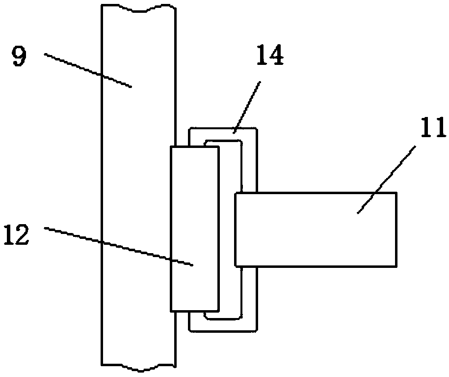
[0029] Example three, reference Figure 1-4 , The outer walls on both sides of the connecting rod 9 are connected to the clamping roller shaft 12 through the sliding groove 18, and the outer diameter of the clamping roller shaft 12 is equal to the inner diameter of the sliding groove 18, and the clamping roller shaft 12 and the sliding groove 18 The rolling connection can play the role of limit clamping on the telescopic movement process of the connecting rod 9 and avoid the phenomenon of offset and shaking of the connecting rod 9.


PUM


Abstract

The invention discloses an industrial pressure vessel convenient to move. The industrial pressure vessel convenient to move comprises a tank body and a base, the tank body is welded to the upper surface of the base, and a gas pressure meter is arranged at the center of the upper surface of the tank body. A gas circuit channel is welded to the outer surface wall of one side of the tank body, and cushion blocks are symmetrically welded to the two sides of the bottom of the base. A driving air cylinder is fixed to the top end of the inner surface wall of the base in a bolted mode, the lower portion of the driving air cylinder is connected with a connection rod through a telescopic rod, and a universal wheel is movably connected to the bottom of the connection rod. A groove is formed in the position, below the driving air cylinder, in the base, and limiting rods are welded to the inner surface walls of the vertical ends of the two sides of the groove. Supports are symmetrically welded to the outer surface wall of the two sides of the limiting rods, and the inner surface walls of the two supports are rotatably connected with clamping roll shafts. In the industrial pressure vessel convenient to move, the overall structural design is simple and reasonable, convenient moving operation is realized, the abrasion at the moving connection portion of the industrial pressure vessel is lowered, and high practicability is achieved.

Description

Technical field [0001] The invention relates to the technical field of industrial pressure vessels, in particular to an industrial pressure vessel that is easy to move. Background technique [0002] Pressure vessel is a kind of airtight vessel that can withstand pressure. The use of pressure vessel is extremely wide. It has an important position and function in many sectors such as industry, civil, military and many fields of scientific research. Among them, it is used in chemical industry and petroleum industry. The most used in the chemical industry, the pressure vessels used in the petrochemical industry alone account for about 50% of the total number of pressure vessels. Pressure vessels are in the chemical and petrochemical industries and are mainly used for heat transfer, mass transfer, reaction and other processes , As well as storage and transportation of pressurized gas or liquefied gas, it also has a wide range of applications in other industrial and civil fields. [000...

Claims


Application Information

Patent Timeline
IPC IPC(8): F16J12/00F16M3/00F16N1/00
CPCF16J12/00F16M3/00F16N1/00
Inventor 张凯帆
Owner 张凯帆
Why Eureka
Try Eureka