Circulating feeder

A feeder and tray technology, which is used in the stacking of objects, destacking of objects, conveyors, etc., can solve the problems of reducing production efficiency, increasing the number of shutdowns and changing materials, and spending more time, so as to achieve fast material changing. and loading and unloading operations, improve production efficiency, and save space.

Pending Publication Date: 2018-11-09
SHENZHEN HANJIANG AUTOMATION SCI & TECH CO LTD
View PDF0 Cites 4 Cited by
  • Summary
  • Abstract
  • Description
  • Claims
  • Application Information

AI Technical Summary

Problems solved by technology

[0006] 1. When changing the tray, it is necessary to send the tray at the working position to the empty tray position first, and then take the tray from the upper tray, which takes a lot of time;
[0007] 2. Putting the plate, taking the plate intelligently goes to the top or bottom plate, and cannot be picked and placed at will, so only one material can be loaded and unloaded, and it cannot cope with automatic loading and unloading of multiple materials
Under the condition of a certain height, the number of trays carried by this kind of feeder will inevitably decrease, which will increase the number of shutdowns and refueling, and reduce production efficiency; and the feeding speed is limited by the overall running speed of the material box

Method used


Image

  • Circulating feeder
  • Circulating feeder
  • Circulating feeder

Examples


Embodiment 1

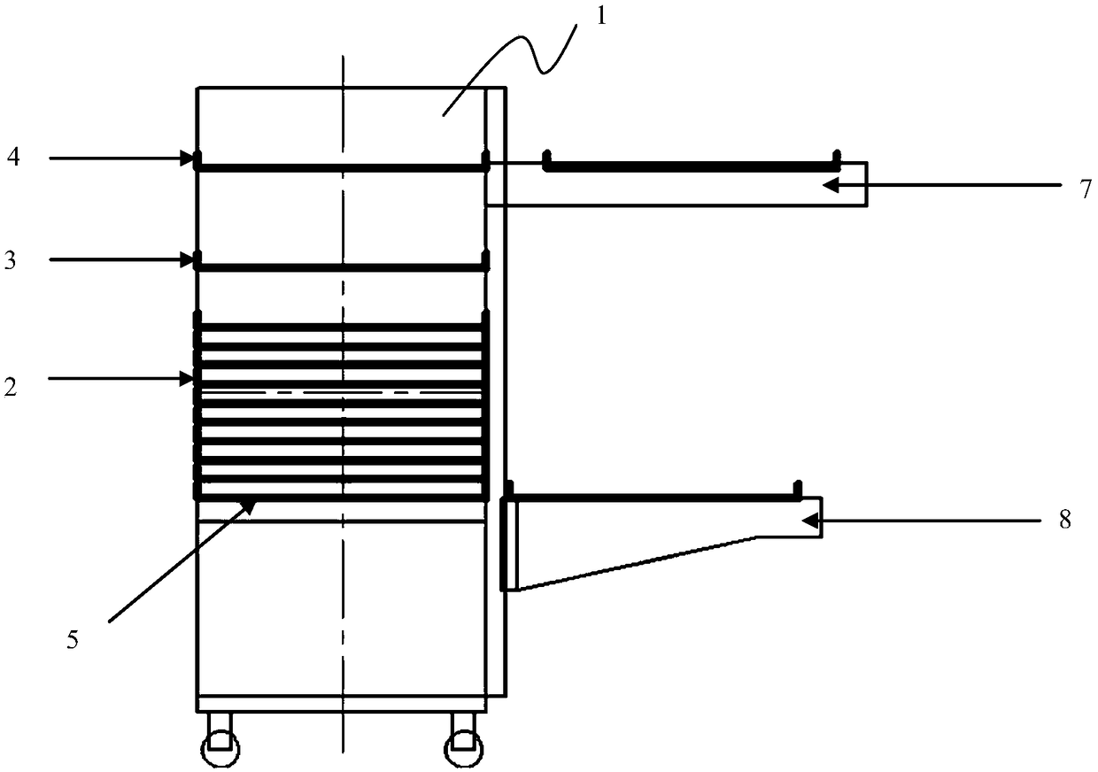
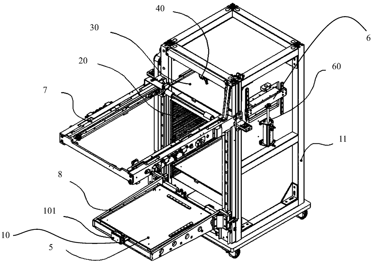
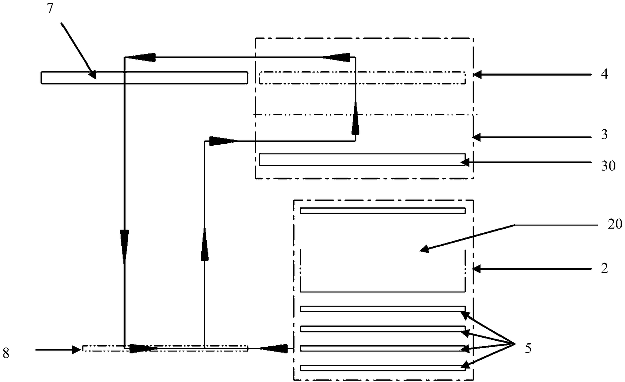
[0031] Such as Figure 1-3 The shown circulation feeder includes a device main body 1, on which a storage area 2, a temporary storage area 3 and a material waiting area 4 are arranged from top to bottom or from bottom to top, and a plurality of The trays 5 used to hold materials are layered and stored in each storage layer in the storage area 2, and the temporary storage area 3 is provided with a device for moving the trays 5 up and down from the temporary storage area 3 to the waiting area. The lifting device 6 of the material area 4 is provided with a conveying device 40 in the material area 4 .

[0032] It also includes a fixed arm 7 and a movable arm 8 arranged on the same side of the device main body 1, the fixed arm 7 is on one side of the waiting area 4, and the fixed arm 7 is provided with a host working position, so The movable arm 8 moves up and down through a traction device (not shown in the figure), and the movable arm 8 is provided with a horizontally moving dis...

Embodiment 2

[0051] On the basis of Embodiment 1, the following driving and transmission modes are preferred.

[0052] Preferably, said fetching and placing mechanism 10 adopts motor drive, belt transmission or screw rod transmission, and said taking and placing mechanism 10 is provided with a vacuum suction device or air claw clamping device for taking and placing discs for pushing, Pull tray 5.

[0053] Preferably, the traction device adopts motor drive, belt drive or screw drive, so as to drive the boom 8 to move up and down.

[0054] Preferably, the jacking device is driven by a cylinder or a motor to drive a screw, so as to lift the tray 5 from the temporary storage area 3 to the waiting area 4 .

[0055] Preferably, the conveying device adopts a motor-driven single-axis manipulator, and the single-axis manipulator grabs the tray 5, or adopts a belt drive, so as to send the tray 5 from the waiting area 4 to the working position 10 of the main machine.

[0056] Such as Figure 2-3 S...


PUM


Abstract

A circulating feeder comprises a stereoscopic storage area, a temporary storage area, a waiting area, a fixed arm and a movable arm. During working, the movable arm moves to one side of the storage area, material discs are pulled out from corresponding storage layers in the storage area to the movable arm, then the movable arm moves to one side of the temporary storage area, the material discs areconveyed from the movable arm into the temporary storage area, automatically move from the temporary storage area to the waiting area and then are conveyed from the waiting area to main machine working stations on the fixed arm for taking operation; and when the discs need to be replaced, the movable arm moves to the position near the fixed arm, the treated material discs are taken out from the main machine working stations and move to one side of the storage area to be conveyed into the storage area, and the action cycle is repeated. According to the circulating feeder, the material discs ofdifferent materials can be stored in the storage area, non-stop automatic switching of the various materials is achieved, through cooperative action of the movable arm and the temporary storage area,quick feeding and discharging operation is achieved, the production efficiency is improved, and through stereoscopic up-down arrangement, the occupied space of the circulating feeder is saved.

Description

technical field [0001] The invention relates to the mechanical field, in particular to a circulating feeder, which can be applied to the electronics industry, 3C industry, food industry and automobile industry. Background technique [0002] There are mainly two types of loading and unloading trolleys on the market according to the placement of the trays: flat type and three-dimensional type. [0003] The main structure of the flat loading and unloading trolley is a tray loading position, an empty tray position, and a working position. , Discharging tray. [0004] The main structure of the three-dimensional loading and unloading car is that the material tray is pulled by a boom that can move up and down, and the material level on the material tray and the empty material tray move back and forth. When changing the material, the boom first sends the empty material tray to the Empty the tray position, then go to the tray upper tray to take the tray, and then send it to the wor...

Claims


Application Information

Patent Timeline
Patent Type & Authority Applications(China)
IPC IPC(8): B65G47/04B65G60/00
CPCB65G47/04B65G60/00B65G2201/0258
Inventor 杨智军徐国根张金楼
Owner SHENZHEN HANJIANG AUTOMATION SCI & TECH CO LTD
Why Eureka
Try Eureka