
Throwing glass breaking ball

A glass-breaking and body-based technology, applied in life-saving equipment, building rescue, etc., can solve the problems of glass-breaking rescue personnel injury, equipment use, and inability to use large areas, and achieve the effects of reduced contact area, high efficiency, and high safety

Inactive Publication Date: 2018-11-09
平裕(成都)科技有限公司
View PDF0 Cites 7 Cited by
  • Summary
  • Abstract
  • Description
  • Claims
  • Application Information

AI Technical Summary

Problems solved by technology

[0003] However, when encountering high-rise buildings such as glass curtain walls and glass ceilings that are inaccessible to personnel, how to break the tempered glass at high places, whether it is trapped people or rescue firefighters, has no way to start; When a fire breaks out, glass breaking at close range may cause damage to glass breaking rescuers
In some special occasions, special equipment such as firearms can be used to break glass, but due to the control of special equipment, it cannot be used in large areas.

Method used


Image

  • Throwing glass breaking ball
  • Throwing glass breaking ball
  • Throwing glass breaking ball

Examples


Embodiment 1

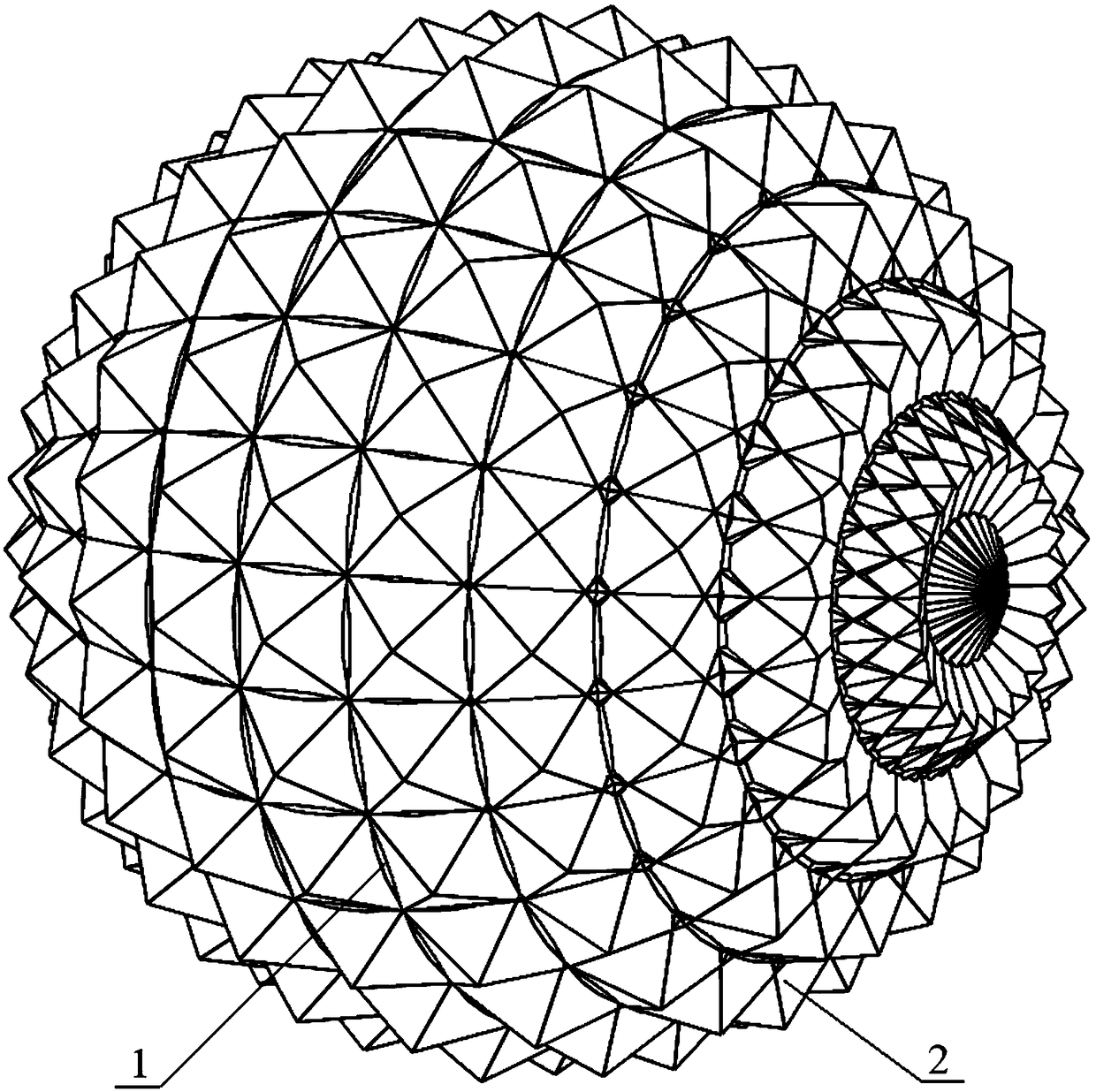
[0029] like Figure 1-Figure 2 As shown, a throwing glass-breaking ball includes a spherical body 1, and protrusions 2 uniformly distributed on the outer surface of the body 1, the hardness of the body 1 and the protrusions 2 are higher than that of tempered glass hardness.

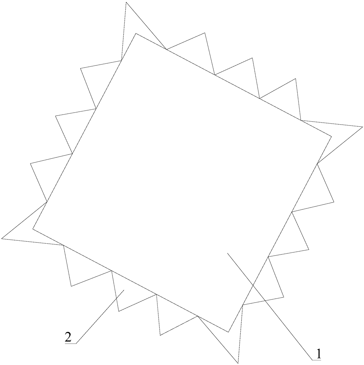
[0030] figure 2 The protrusions 2 shown in are pyramid structures, all the protrusions 2 have the same size, and the cone angles θ of all the protrusions 2 are greater than or equal to 20 degrees and less than or equal to 160 degrees.

[0031] Preferably, the body 1 and the protrusion 2 have the same hardness, and the body 1 and the protrusion 2 are integrally formed structural parts.

[0032] Preferably, the protrusion 2 is a zirconia-toughened alumina ceramic (ZTA) structure, and the body 1 can also adopt this ceramic structure, wherein the addition ratio can be selected as 10%-30% zirconia and 70% -90% alumina. In actual production, the addition ratio is determined according to the performance of v...

Embodiment 2

[0034] like image 3 As shown, the difference between this embodiment and embodiment 1 is that the body 1 is a cuboid structure.

Embodiment 3

[0036] like Figure 4 As shown, the difference between this embodiment and Embodiment 1 is that the body 1 has a regular octagonal prism structure. On the surface of the body 1, there are a variety of protrusions 2 of different materials, different hardness and different sizes. By optimizing the design of the protrusions 2, a variety of glass breaking balls with different performances are formed to meet the actual glass breaking needs. .


PUM

PropertyMeasurementUnit
Cone angleaaaaaaaaaa

Abstract

The invention discloses a throwing glass breaking ball. The throwing glass breaking ball comprises a body, and a plurality of bulges arranged on the outer surface of the body, and the bulges are the members with the hardness higher than the hardness of the tempered glass. When the glass breaking operation is required, the glass breaking ball can be thrown into the tempered glass by hands or usinga device, because the hardness of the bulges on the glass breaking ball is higher than that of the tempered glass, and when the bulges hit the glass surface, the stress limit of the tempered glass surface is broken through, the tempered glass is broken, and the glass breaking purpose is achieved. When the glass breaking ball is used for breaking the glass, because the bulges are arranged on the outer surface of the body, the glass breaking can be achieved without the high throwing speed through the shape bulges making contact with the glass, and the advantages of being high in efficiency, lowin impact speed and high in safety are achieved; and the long-distance glass breaking can be achieved through a throwing way, and when the glass breaking rescue is needed during the fire in high-risebuildings and other, the personnel safe rescue and rapid rescue can be achieved.

Description

technical field [0001] The invention relates to a glass breaking tool, in particular to a throwing glass breaking ball. Background technique [0002] Tempered glass is widely used in building curtain walls and various vehicles. Due to the high hardness of tempered glass, it is difficult to break the tempered glass after a safety accident, and professional glass breaking tools are required. In daily life, glass-breaking tools can be seen everywhere, and have become one of the important tools to ensure the safety of personnel. For example, on buses, subways and other means of transportation, equipped with safety hammers or automatic glass-breaking devices, the objects of use of such tools are often It is the trapped person himself, and they are all close-contact glass-breaking tools. [0003] However, when encountering high-rise buildings such as glass curtain walls and glass ceilings that are inaccessible to personnel, how to break the tempered glass at high places, whether ...

Claims


Application Information

Patent Timeline
IPC IPC(8): A62B3/00
CPCA62B3/00
Inventor 黄裕中徐庆忠魏宇科
Owner 平裕(成都)科技有限公司
Learn More