
Dual-input and high-gain Boost converter

A high-gain, dual-input technology, applied in the direction of converting DC power input to DC power output, output power conversion devices, conversion equipment without intermediate conversion to AC, etc., can solve the problem of poor anti-interference ability, large current ripple, etc. question

Pending Publication Date: 2018-11-06
TIELING POWER SUPPLY COMPANY OF STATE GRID LIAONING ELECTRIC POWER COMPANY +1
View PDF1 Cites 1 Cited by
  • Summary
  • Abstract
  • Description
  • Claims
  • Application Information

AI Technical Summary

Problems solved by technology

[0003] The purpose of the present invention is to provide a dual-input high-gain Boost converter for the above-mentioned problems in the prior art, which solves the problems of poor anti-interference ability and large current ripple of the Boost converter in the prior art

Method used


Image

  • Dual-input and high-gain Boost converter
  • Dual-input and high-gain Boost converter
  • Dual-input and high-gain Boost converter

Examples


Embodiment

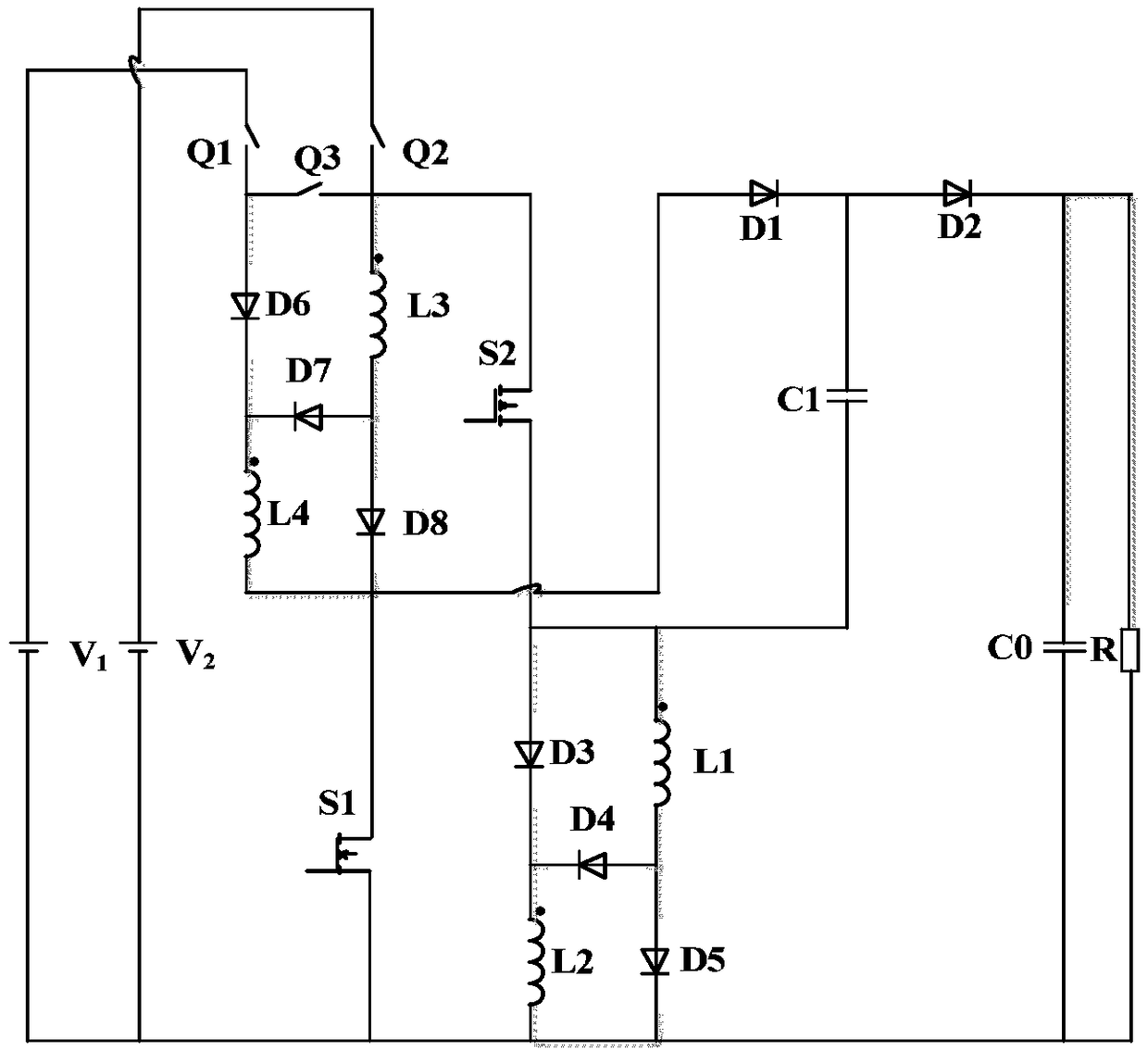
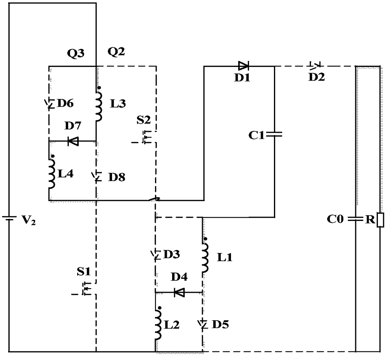
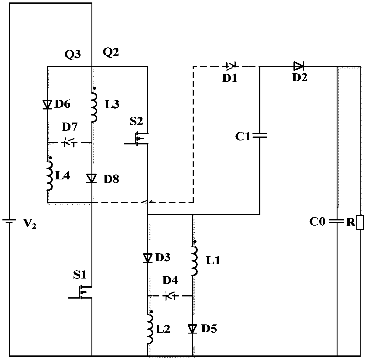
[0017] The invention relates to a double-input high-gain Boost converter. Such as figure 1 shown, the DC input supply V 1 , DC input power supply V 2 The anode of the switch Q1 and one end of the switch Q2 are respectively connected, the other end of the switch Q1 is connected with one end of the switch Q3 and the anode of the unidirectional rectifier diode D6, and the other end of the switch Q2 is connected with the other end of the switch Q3 and one of the coupled inductor The terminal with the same name of the winding L3 is connected to the drain of the power switch S2, the other end of the winding L3 of the coupled inductor is connected to the anodes of the unidirectional rectifier diode D7 and the unidirectional rectifier diode D8, and the cathode of the unidirectional rectifier diode D6 is connected to the unidirectional rectifier diode D6. The cathode of the diode D7 is connected to the terminal of the same name of a winding L4 of the coupled inductor, the cathode of ...


PUM


Abstract

The invention discloses a dual-input and high-gain BOOST converter. The dual-input high-gain Boost converter comprises two DC input sources, a variable-structure switch block composed of three switches, two power switch tubes, a coupling inductor with four windings, eight one-way rectifier diodes, and an output filter capacitor. Compared with the existing BOOST converter, the dual-input and high-gain BOOST converter disclosed by the invention still can work as normal when one DC input source cannot work as normal; under the same duty ratio, the greater boosting transformation ratio is provided, the power switch tube voltage stress is low, the control policy is simple, and the volume is small.

Description

technical field [0001] The invention relates to a DC-DC converter, in particular to a Boost converter with double input and high voltage gain characteristics. Background technique [0002] Due to the excessive consumption and use of non-renewable energy, and the environmental pollution problems caused by non-renewable energy, new energy generation methods such as solar power generation and wind power generation have been greatly developed. Both solar power and wind power need to be connected to the common bus through a Boost converter. High-gain Boost converters are widely used because of their simple structure and convenient operation. Therefore, higher requirements are put forward for the output voltage range of the high-gain Boost converter. However, the voltage gain of the traditional Boost converter is low, which cannot meet the needs of actual work. In order to solve this problem, the patent publication number CN102594134A discloses a single-switch high-gain Boost co...

Claims


Application Information

Patent Timeline
IPC IPC(8): H02M3/04H02M3/155
CPCH02M3/04H02M3/155H02M1/0083
Inventor 袁野王秋实孙威吴亮曹鹏魏大庆刘宇
Owner TIELING POWER SUPPLY COMPANY OF STATE GRID LIAONING ELECTRIC POWER COMPANY
Learn More