
A Test Method for Dynamic Resistance of Vertically Layered Soil

A technology of dynamic resistance and vertical layering, which is applied in the direction of measuring resistance/reactance/impedance, measuring electrical variables, instruments, etc., can solve the problems of difficult accurate calculation of impact grounding resistance and complex dynamic resistance characteristics, and achieve the effect of convenient operation

Active Publication Date: 2019-07-12
SOUTHWEST JIAOTONG UNIV
View PDF10 Cites 0 Cited by
  • Summary
  • Abstract
  • Description
  • Claims
  • Application Information

AI Technical Summary

Problems solved by technology

At present, domestic research on soil dynamic resistance characteristics mainly uses computer simulation to simulate the dynamic process of soil resistance and the phenomenon of spark discharge, and the dynamic resistance characteristics of soil resistance under impact current are affected by many factors, such as: impact current amplitude, Soil composition and structure, pH, water content, temperature, external electric field strength, etc. These factors make the dynamic resistance characteristics of the soil under the action of high frequency and large impact current more complicated, and also make it difficult to accurately calculate the impact grounding resistance of the tower grounding device

Method used


Image

  • A Test Method for Dynamic Resistance of Vertically Layered Soil
  • A Test Method for Dynamic Resistance of Vertically Layered Soil
  • A Test Method for Dynamic Resistance of Vertically Layered Soil

Examples


Embodiment Construction

[0041] The present invention will be further described below in conjunction with accompanying drawing.

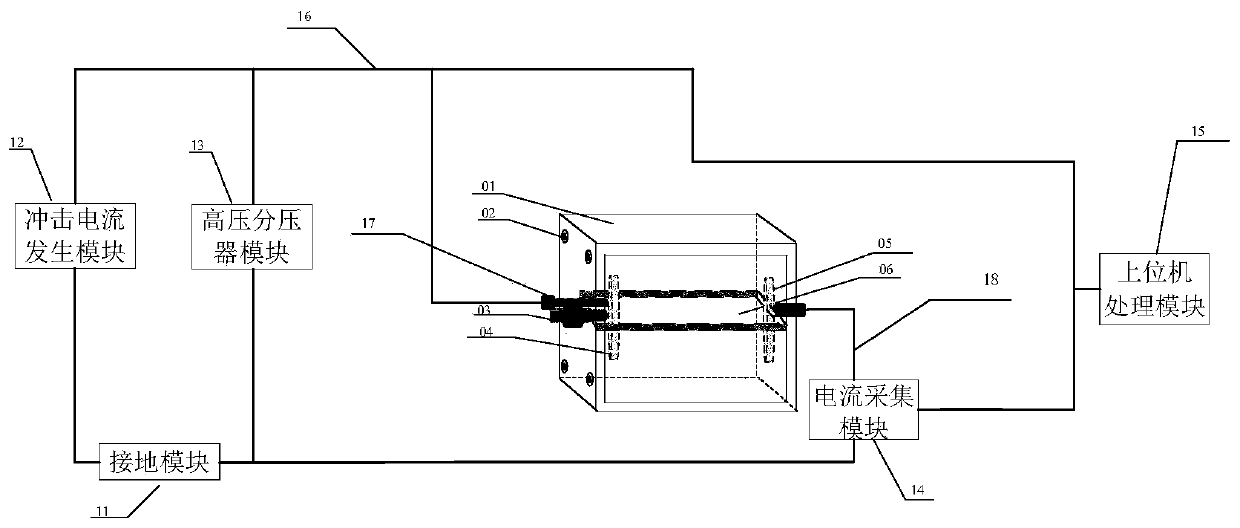
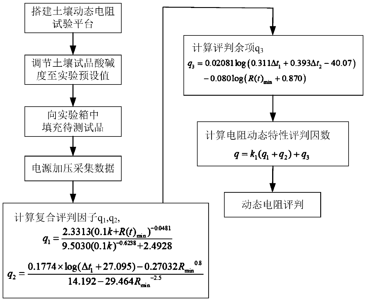
[0042] Depend on figure 1 , figure 2 It can be seen that the test platform and method provided by the present invention comprise the steps:

[0043] Step 1: Build a vertical layered soil dynamic resistance test platform

[0044] The test platform includes a test box (01); a slotted screw (02); a left copper electrode (04) is provided on the left side wall of the test box (01), and an operating mechanism (03) for controlling the lateral movement of the left copper electrode (04) ); the right side wall of the test box (01) is also provided with a right copper electrode (05); the left copper electrode (04) and the right copper electrode (05) are both vertical discs; it also includes an insulating partition (06), a grounding Module (11), Impulse Current Generation Module (12), High Voltage Divider Module (13), Current Acquisition Module (14), Host Computer Processing Module (...


PUM


Abstract

The invention relates to a vertical layered soil dynamic resistance test method. The test method comprises the following steps: a vertical layered soil dynamic resistance test platform is built, and aleft copper electrode and a right copper electrode are arranged on the left side wall and the right side wall of a test box of the test platform; the output end of an impact current generation moduleis connected with the high-voltage end of a high-voltage voltage divider module; the high-voltage end of the high-voltage voltage divider module is connected with the left copper electrode; the rightcopper electrode is connected with the grounding end of the impact current generation module; the grounding end of the impact current generation module is connected to a grounding module; a current acquisition module is used for measuring current flowing through the left copper electrode and the right copper electrode; and when an insulating partition plate is inserted into an experiment box, theexperiment box is divided into more than two spaces from bottom to top. The test method also comprises the steps of measuring the pH value of a soil test product, filling vertical layered soil, measuring the voltage and the current of a soil sample at the current pH value and evaluating the dynamic resistance of the soil. By the vertical layered soil dynamic resistance test method, the surrounding soil vertical layered working condition of the grounding system can be effectively simulated and the dynamic resistance of the soil can be evaluated accurately.

Description

technical field [0001] The invention belongs to the technical field of electric power system grounding, and in particular relates to a test method for dynamic resistance of vertically layered soil. Background technique [0002] When the transmission line tower is struck by lightning, due to the existence of the grounding resistance of the tower, the top of the tower will generate a high potential. Excessively high potential will cause the tower to counterattack the transmission line, thereby causing a short circuit of the transmission line, reducing the stability of the power system and reliability. The main function of the transmission line tower grounding device is to effectively discharge the lightning current into the ground when the tower top or the lightning protection line is struck by lightning, so the current flowing through the grounding device is mainly the lightning impulse current. When a large impact current is injected, the soil resistivity will decrease, and...

Claims


Application Information

Patent Timeline
Patent Type & Authority Patents(China)
IPC IPC(8): G01R27/08
CPCG01R27/08
Inventor 周利军徐晗王路伽王朋成刘彬
Owner SOUTHWEST JIAOTONG UNIV
Learn More