
Heat supply pipeline leakage detection system and method based on infrasound waves and reference point

A heating pipeline and leakage detection technology, which is applied in the pipeline system, detects the appearance of fluid at the leakage point, and uses the liquid/vacuum degree to measure the liquid tightness, etc. It can solve the problems of the influence of calculation results and the non-constant speed of sound waves, etc. , to achieve the effect of reducing the workload of on-site investigation and improving the calculation accuracy

Pending Publication Date: 2018-11-06
TAIYUAN UNIV OF TECH
View PDF0 Cites 9 Cited by
  • Summary
  • Abstract
  • Description
  • Claims
  • Application Information

AI Technical Summary

Problems solved by technology

However, the infrasonic wave method needs to consider the propagation speed of the sound wave when calculating the location of the leak point. Due to the frequent changes in the temperature, pressure, density and other working conditions of the heating pipeline, the speed of the sound wave is not constant, which has a great impact on the calculation results.

Method used


Image

  • Heat supply pipeline leakage detection system and method based on infrasound waves and reference point
  • Heat supply pipeline leakage detection system and method based on infrasound waves and reference point
  • Heat supply pipeline leakage detection system and method based on infrasound waves and reference point

Examples


Embodiment Construction

[0038] In order to enable those skilled in the art to better understand the technical solutions in the embodiments of the present invention, and to make the above-mentioned purposes, features and advantages of the embodiments of the present invention more obvious and understandable, the following describes the technical solutions of the present invention through the accompanying drawings and embodiments The technical solution is further described in detail.

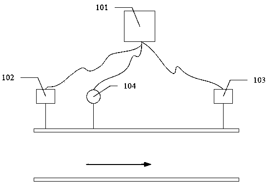
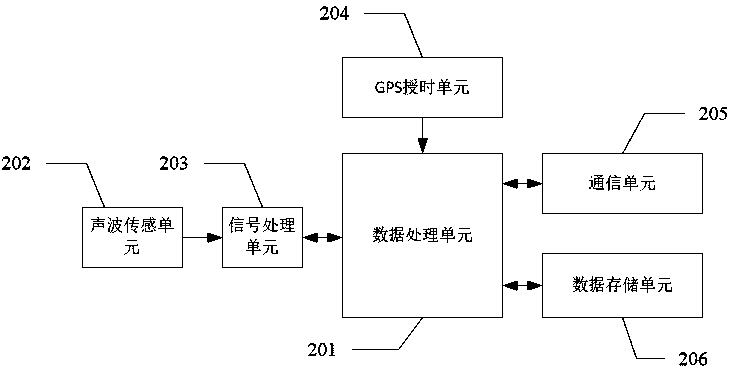
[0039] The present invention relates to a heating pipeline leakage monitoring system based on infrasonic waves and reference points, as attached figure 1 The heating pipeline leakage detection system includes: a central control system 101 , an upstream acoustic wave monitoring device 102 , a downstream acoustic wave monitoring device 103 and a sound source device 104 . The central control system 101 has a built-in third GPS timing unit. Wherein, the distance between the upstream acoustic wave monitoring device 102 and th...


PUM


Abstract

The invention belongs to the technical field of pipeline leakage detection, in particular to a heat supply pipeline leakage detection system based on infrasound waves and a reference point. The heat supply pipeline leakage detection system comprises a center control system, an upstream acoustic wave monitoring device, a downstream acoustic wave monitoring device and an acoustic source device. Thedistance between the upstream acoustic wave monitoring device and the downstream acoustic wave monitoring device is fixed. The acoustic source device is located on a pipeline between the upstream acoustic wave monitoring device and the downstream acoustic wave monitoring device, and the distance between the acoustic source device and the upstream acoustic wave monitoring device is fixed. The upstream acoustic wave monitoring device, the downstream acoustic wave monitoring device and the acoustic source device are all connected with the center control system through wired network or wireless network for two-way data communication. According to the heat supply pipeline leakage detection system based on the infrasound waves and the reference point, the velocity of acoustic wave propagation inthe pipeline can be measured online by detecting an acoustic wave signal emitted from the reference point, when a pipeline leakage accident occurs, the calculation accuracy of a leakage location canbe significantly improved by calculating the leakage location at the acoustic wave transmission velocity, and the site survey workload of maintenance personnel is greatly reduced.

Description

technical field [0001] The invention belongs to the technical field of pipeline leakage detection, in particular to a heating pipeline leakage detection system and method based on infrasonic waves and reference points. Background technique [0002] At present, most cities or regions use centralized heating. The total heating area of ​​many heating systems has reached tens of millions of square meters. The heating pipeline is an important part of the heating system, but it is also the weakest in reliability. link. With the increase of the temperature and pressure parameters of the heating medium, the extension of the service time of the heating pipeline, and the influence of many factors such as the aging of the pipeline material, the way of laying, the working environment, and the construction method, the leakage of the heating pipeline continues to occur. The stable and safe operation of the thermal system has brought a great impact and also caused great economic losses. ...

Claims


Application Information

Patent Timeline
IPC IPC(8): F17D5/06G01M3/24
CPCF17D5/06G01M3/24
Inventor 王丽艳贺敏程兰乔铁柱阎高伟
Owner TAIYUAN UNIV OF TECH
Learn More