Engine cylinder block and cylinder block oil-gas separation assembly

A technology of engine block and engine oil, which is applied in the direction of engine components, machines/engines, cylinders, etc., can solve problems such as unreasonable layout of oil-gas separation system, reduce the risk of icing, avoid production costs and height dimensions, increase The effect of processing difficulty

Inactive Publication Date: 2018-11-06
CHONGQING SOKON IND GRP CO LTD
View PDF5 Cites 0 Cited by
  • Summary
  • Abstract
  • Description
  • Claims
  • Application Information

AI Technical Summary

Problems solved by technology

[0005] The purpose of the present invention is to provide an engine cylinder block and cylinder oil-gas separation assembly in view of the unreasonable layout of the oil-gas separation system in the prior art

Method used


Image

  • Engine cylinder block and cylinder block oil-gas separation assembly
  • Engine cylinder block and cylinder block oil-gas separation assembly
  • Engine cylinder block and cylinder block oil-gas separation assembly

Examples


Embodiment 1

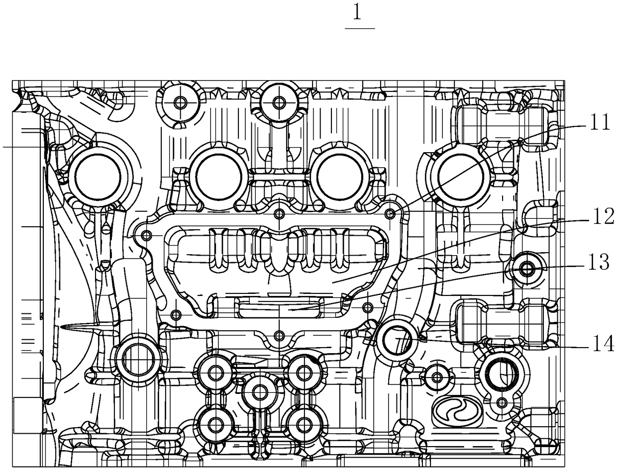
[0024] see figure 1 . This embodiment provides an engine block 1 , which is provided with an oil-air separation installation cavity 12 ; the oil-air separation installation cavity 12 is used for installing the oil-air separator 2 . In the solution provided by the present invention, an oil-air separation installation chamber 12 for installing the oil-air separator 2 is provided on the engine block 1 . When in use, the oil-gas separator 2 can be installed in the oil-gas separation installation chamber 12, so that the oil-gas mixture can quickly enter the oil-gas separator 2, reducing the risk of freezing. And because the engine block 1 is molded by casting, therefore, the oil-gas separation installation chamber 12 is set on the engine block 1, which will neither increase the height of the whole machine nor excessively increase the processing difficulty of the engine block 1, which is beneficial to reduce the engine block 1. Overall production cost and height dimensions.

[00...

Embodiment 2

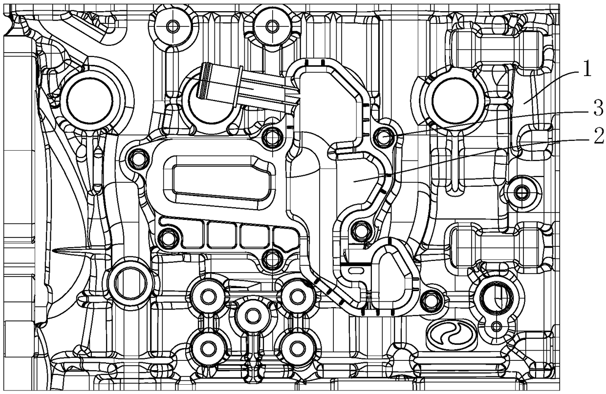
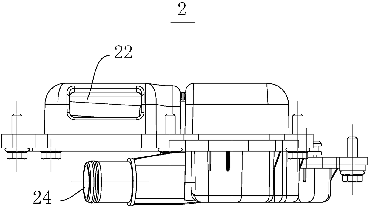
[0031] see Figure 2-4 . This embodiment provides a cylinder oil-air separation assembly, including an oil-air separator 2 and an engine block 1; the engine block 1 is provided with an oil-air separation installation cavity 12, and the oil-air separator 2 is located in the oil-air separation installation cavity 12 and is connected to the engine block 1. The engine is connected; the oil-gas separation channel 22 is formed on the oil-gas separator 2, and one end of the oil-gas separation channel 22 is an inlet, and the inlet of the oil-gas separation channel 22 is connected with the crankcase of the engine. Through the cylinder oil-air separation assembly provided by the present invention, the oil-air mixture can quickly enter the oil-air separator 2 during use, reducing the risk of freezing. And because the engine block 1 is mostly formed by casting, the above structure will neither increase the height of the whole machine nor excessively increase the processing difficulty of ...


PUM


Abstract

The invention relates to the field of automobile accessories, in particular to an engine cylinder block and a cylinder block oil-gas separation assembly. The engine cylinder block is provided with anoil-gas separation installation cavity, and the oil-gas separation installation cavity is used for allowing an oil-gas separator to be installed inside. The cylinder block oil-gas separation assemblycomprises the oil-gas separator and the engine cylinder block, the oil-gas separation installation cavity is formed in the engine cylinder block, the oil-gas separator is located in the oil-gas separation installation cavity and is connected with an engine, an oil-gas separation channel is formed in the oil-gas separator, and one end of the oil-gas separator channel is connected with an engine crankcase. According to the provided engine cylinder block and the cylinder block oil-gas separation assembly, an oil-gas mixture can quickly enter the oil-gas separator, so that the freezing risk is reduced, and the machining difficulty of an engine cylinder cover can be further reduced.

Description

technical field [0001] The invention relates to an automobile accessory, in particular to an engine cylinder block and an oil-gas separation assembly for the cylinder block. Background technique [0002] At present, there are two main arrangements of engine oil-air separation systems on the market, one is to integrate the oil-air separator in the cylinder head cover, and the other is to connect the oil-air separation system externally to the cylinder head cover. [0003] The layout of the oil-air separator integrated in the cylinder head cover increases the design complexity of the cylinder head cover, and at the same time, due to the existence of the oil-air separation system, a larger layout space is required, which increases the height of the whole machine. [0004] The layout of the oil-air separation system connected to the cylinder head cover, because the oil-air mixture in the cylinder head oil chamber needs to pass from the cylinder head cover through the outlet pipe...

Claims


Application Information

Patent Timeline
Patent Type & Authority Applications(China)
IPC IPC(8): F02F1/18F01M13/04
CPCF02F1/18F01M13/04
Inventor 凌青海李金印唐德润
Owner CHONGQING SOKON IND GRP CO LTD
Why Eureka
Try Eureka