
Novel pneumatic light lift

A lift and light-weight technology, which is applied in the field of lifts, can solve the problems of high production cost, large floor space, complex equipment structure, etc., and achieve the effect of simple structure, low production cost and small floor space

Pending Publication Date: 2018-11-06
ANHUI BOYI FLUID POWER TRANSMISSION
View PDF9 Cites 5 Cited by
  • Summary
  • Abstract
  • Description
  • Claims
  • Application Information

AI Technical Summary

Problems solved by technology

[0004] The purpose of the present invention is to solve the problems in the prior art that the floor area is large, the equipment structure is complicated, the production cost is high, it is not suitable for use in small production workshops and the lifting platform is easily damaged by rigidity, and a sanding machine is proposed. Scraper device for automatic feeding of boards

Method used

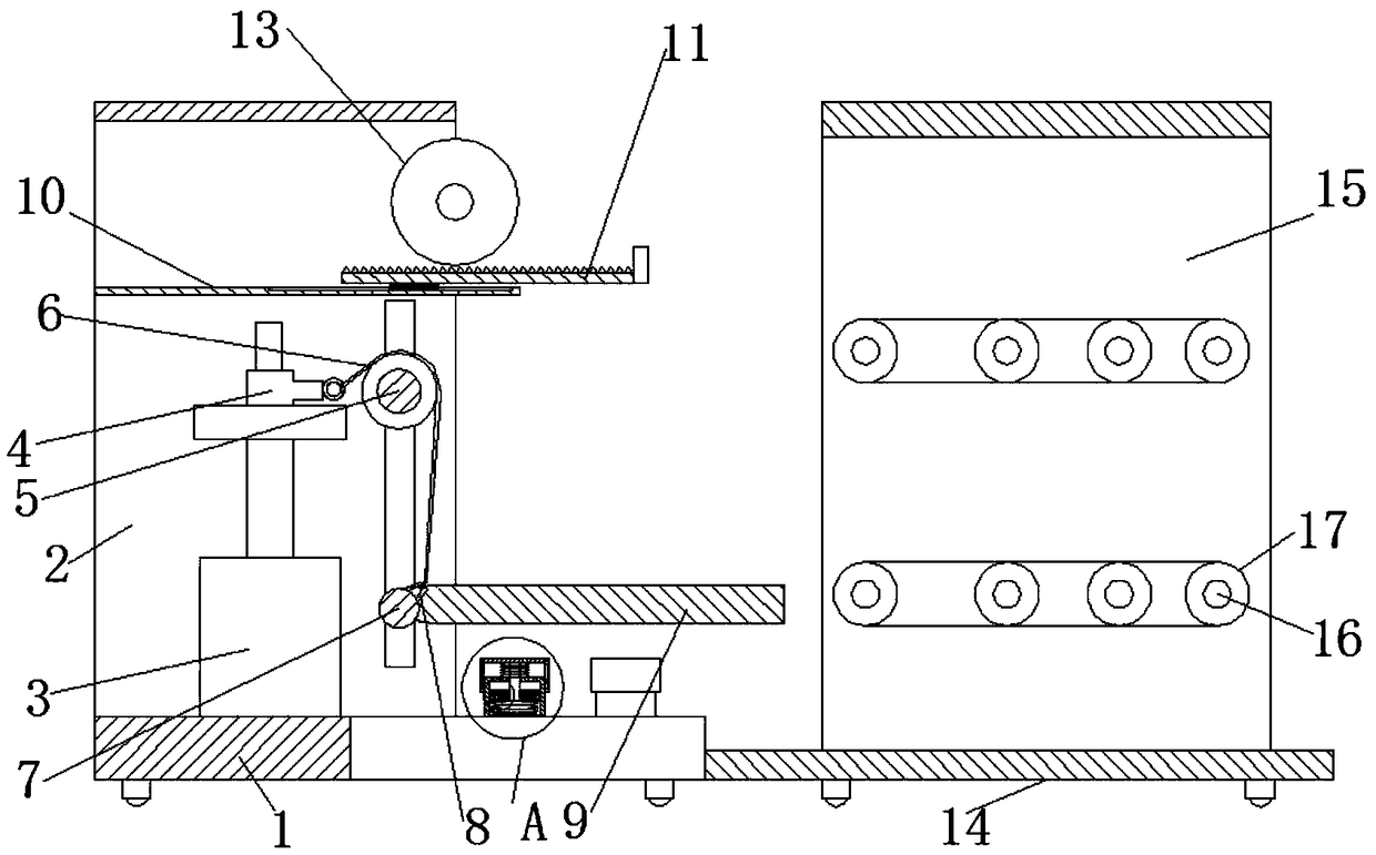

Image

  • Novel pneumatic light lift
  • Novel pneumatic light lift
  • Novel pneumatic light lift

Examples


Embodiment Construction

[0026] The following will clearly and completely describe the technical solutions in the embodiments of the present invention with reference to the accompanying drawings in the embodiments of the present invention. Obviously, the described embodiments are only some, not all, embodiments of the present invention.

[0027] In describing the present invention, it should be understood that the terms "upper", "lower", "front", "rear", "left", "right", "top", "bottom", "inner", " The orientation or positional relationship indicated by "outside", etc. is based on the orientation or positional relationship shown in the drawings, and is only for the convenience of describing the present invention and simplifying the description, rather than indicating or implying that the referred device or element must have a specific orientation, so as to Specific orientation configurations and operations, therefore, are not to be construed as limitations on the invention.

[0028] refer to Figure ...


PUM


Abstract

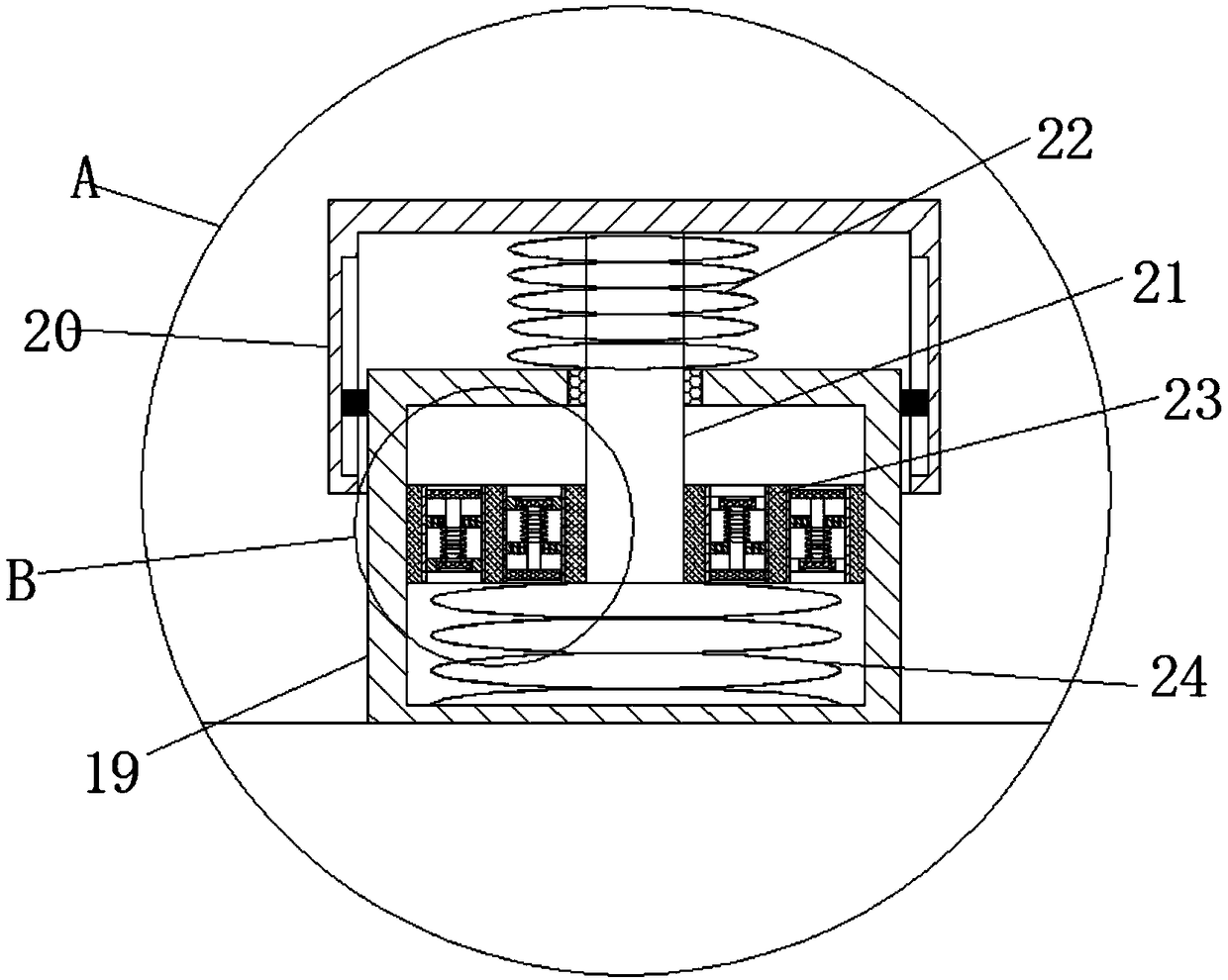
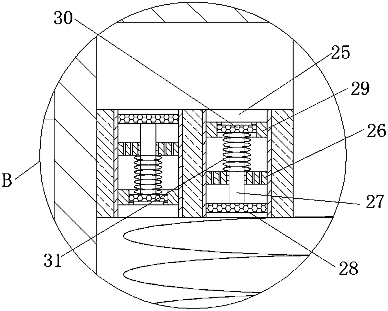
The invention discloses a novel pneumatic light lift. The novel pneumatic light lift comprises a lifting mechanism and a conveying mechanism. The lifting mechanism comprises a chassis fixedly connected with the ground, the upper surface of the chassis is symmetrically and fixedly connected with two supporting plates, the upper surface of the chassis is fixedly connected with a linear air cylinder,an output shaft of the linear air cylinder is fixedly connected with a drive plate, the upper surface of the drive plate is fixedly connected with a first movable rod, the two ends of the first movable rod are slidingly connected with the two supporting plates, the rod walls of the first movable rod are symmetrically and fixedly sleeved with two chain wheels, the same second movable rod is slidingly connected between the two supporting plates, the rod walls of the second movable rod are symmetrically and fixedly sleeved with two fixing rings, and the same chain is wound between the chain wheels and the fixing rings jointly. Automatic loading and unloading can be achieved, the novel pneumatic light lift is small in occupied area, low in production cost and suitable for small workshops, andrigid damage to a lifting platform can be avoided.

Description

technical field [0001] The invention relates to the technical field of lifts, in particular to a novel pneumatic light lift. Background technique [0002] In recent years, with the continuous improvement of my country's industrialization level, mechanized operations have become a major trend in industrial production. In the current industrial production, especially in the transshipment process of some products, most of the operations need to be carried out in a mechanized way. Equipped with automatic lifting mechanism to meet the corresponding operation needs. [0003] In the prior art, most of the multi-cantilever elevators are used. This kind of elevator occupies a large area, the equipment structure is complicated, and the production cost is high. It is not suitable for small production workshops. In the prior art, when the lifting platform falls, it directly Contact with the chassis will cause rigid damage to the lifting platform. Contents of the invention [0004] ...

Claims


Application Information

Patent Timeline
Patent Type & Authority Applications(China)
IPC IPC(8): B66F7/04B66F7/28F16F15/04F16F15/023B65G47/52
CPCF16F15/023F16F15/04B65G47/52B66F7/04B66F7/28
Inventor 邱世平闵玉春张峰军
Owner ANHUI BOYI FLUID POWER TRANSMISSION
Learn More