
Multifunctional lubricating oil filtering device

A technology of filtering device and lubricating oil, which is applied in filtering separation, filtering circuit, gravity filter, etc., can solve the problems of splashing oil droplets, waste, polluting the environment of the factory area, etc. Effect

Inactive Publication Date: 2018-11-06
寅时科技(天津)有限公司
View PDF0 Cites 2 Cited by
  • Summary
  • Abstract
  • Description
  • Claims
  • Application Information

AI Technical Summary

Problems solved by technology

[0002] During the use of lubricating oil, it is necessary to ensure that the lubricating oil is pure and free of impurities, otherwise it will seriously damage the machine, such as roughening of the friction surface, seizure or blockage of the lubricating hole, etc. Therefore, the lubricating oil must be filled with a filter device to remove Impurities are filtered out. When filtering with a traditional filter device, the filter device is first connected to the oil storage tank. Since the filter is hollow before filtering, the lubricating oil will be mixed with a large amount of air after being filtered by the filter, which will easily cause oil droplets to splash and pollute the factory area. At the same time, when the filter device finishes filtering, it is impossible to transport the lubricating oil remaining in the filter device that is not used for filling back to the oil storage tank, and it can only be discharged and recycled, resulting in waste

Method used


Image

  • Multifunctional lubricating oil filtering device
  • Multifunctional lubricating oil filtering device

Examples


Embodiment Construction

[0016] In order to enable those skilled in the art to better understand the technical solutions of the present invention, the present invention will be further described in detail below in conjunction with the accompanying drawings and preferred embodiments.

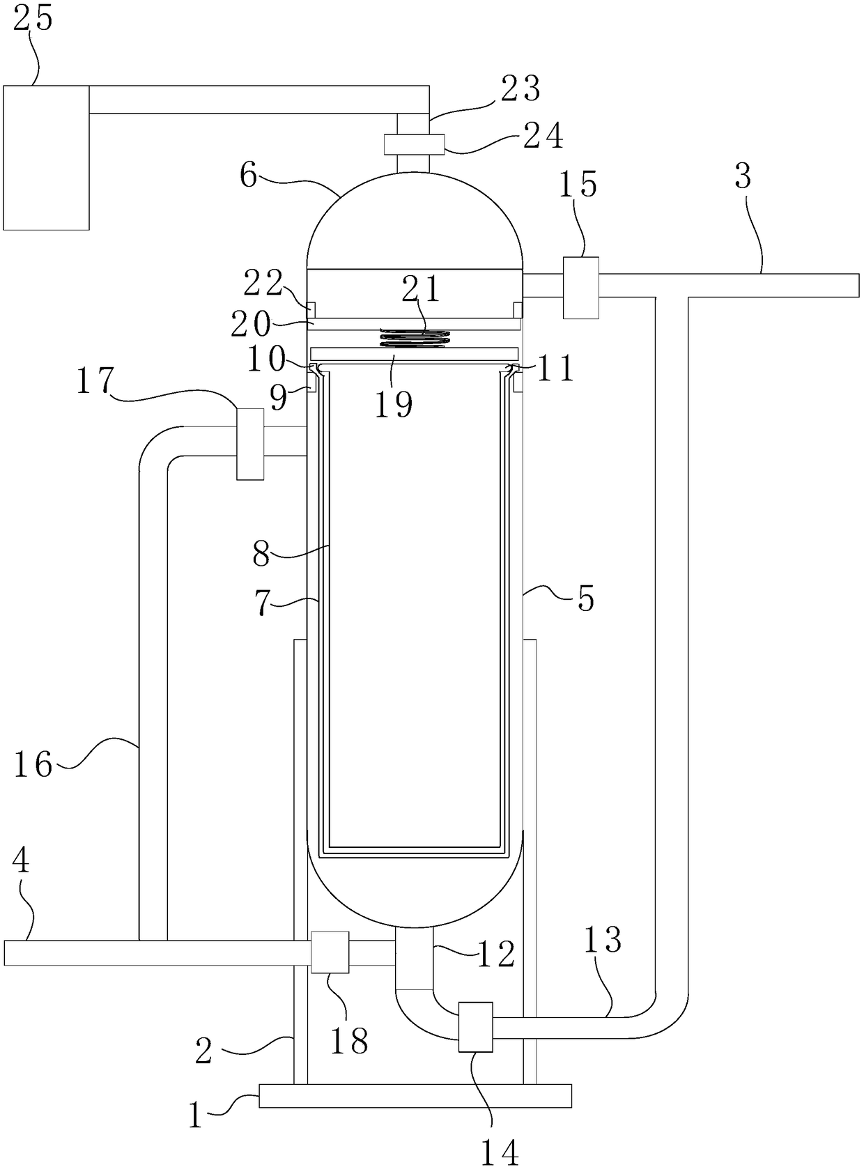
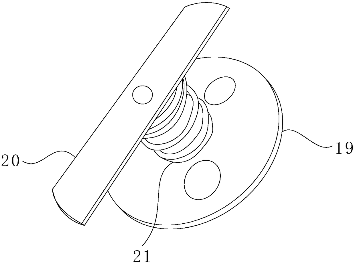
[0017] As shown in the figure, the present invention includes: a support frame, a filter cartridge affixed to the support frame, an oil inlet pipe 3 and an oil outlet pipe 4 respectively connected to the filter cartridge, and the support frame used in this embodiment includes a chassis 1 and a uniform a plurality of vertical support rods 2 fixed on the chassis, the support rods are welded to the outer cylinder,

[0018] The filter cartridge includes an outer cylinder 5, a cylinder cover 6 sealingly connected to the outer cylinder, a filter basket 7 arranged in the outer cylinder and a filter mesh bag 8 arranged in the filter basket. The air delivery pipe 23 is equipped with a gas valve 24, the air delivery pipe is connec...


PUM


Abstract

The invention relates to the field of lubricating oil filtering equipment and in particular relates to a multifunctional lubricating oil filtering device which comprises a support rack, a filtering cylinder, an oil inlet tube and an oil outlet tube, wherein the filtering cylinder is fixedly connected with the support rack; the filtering cylinder comprises an outer cylinder, a cylinder cover whichis connected with the outer cylinder in a sealed manner, a filtering basket arranged inside the outer cylinder, and a filtering net bag which is arranged inside the filtering basket; a gas conveying tube which is communicated with the interior of the filtering cylinder is arranged above the cylinder cover; the gas conveying tube is connected with a gas pump through a hose. The multifunctional lubricating oil filtering device is simple in structure, reasonable to design and convenient to use, lubricating oil can be effectively prevented from being mixed with a great deal of air when passing through the filtering cylinder, and oil droplets are prevented from splashing which can cause factory environment pollution; meanwhile, by controlling valve opening and closure, residual lubricating oilin the filtering cylinder can be pressed back into an oil inlet tube by using the air pump through a first connecting tube and finally flows back into an oil reservoir, and clean recycling of the lubricating oil can be achieved.

Description

technical field [0001] The invention relates to the field of lubricating oil filtering equipment, in particular to a multifunctional lubricating oil filtering device. Background technique [0002] During the use of lubricating oil, it is necessary to ensure that the lubricating oil is pure and free of impurities, otherwise it will seriously damage the machine, such as roughening of the friction surface, seizure or blockage of the lubricating hole, etc. Therefore, the lubricating oil must be filled with a filter device to remove Impurities are filtered out. When filtering with a traditional filter device, the filter device is first connected to the oil storage tank. Since the filter is hollow before filtering, the lubricating oil will be mixed with a large amount of air after being filtered by the filter, which will easily cause oil droplets to splash and pollute the factory area. At the same time, when the filtering device finishes filtering, the lubricating oil remaining in...

Claims


Application Information

Patent Timeline
Patent Type & Authority Applications(China)
IPC IPC(8): B01D29/27B01D29/35B01D29/58B01D35/01
CPCB01D29/27B01D29/35B01D29/58B01D36/001
Inventor 付钰
Owner 寅时科技(天津)有限公司
Learn More