Eureka AIR delivers breakthrough ideas for toughest innovation challenges, trusted by R&D personnel around the world.

A self-locking bracket

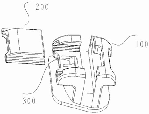
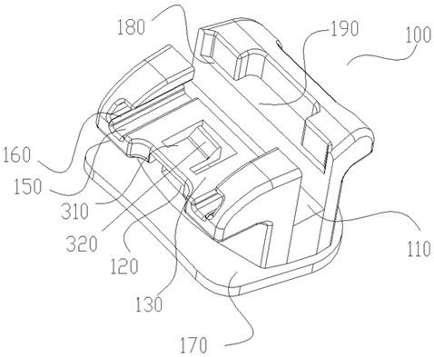
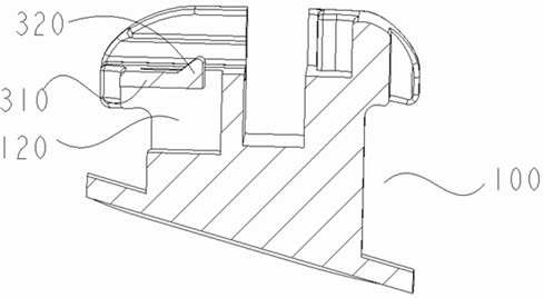
A self-locking bracket and card slot technology, applied in brackets, arch wires, etc., can solve the problems of easy loss of function of the cover body, difficult installation and disassembly, etc., and achieve the effect of convenient treatment work and reliable bracket structure.

Active Publication Date: 2020-12-22
GUANGZHOU OO MEDICAL SCI LTD
View PDF3 Cites 0 Cited by
  • Summary
  • Abstract
  • Description
  • Claims
  • Application Information

AI Technical Summary

Problems solved by technology

[0005] The purpose of the present invention is to provide a more reliable self-locking bracket in order to solve the problems that the cover body is easy to lose its function and difficult to install and disassemble.

Method used


Image

  • A self-locking bracket
  • A self-locking bracket
  • A self-locking bracket

Examples


specific Embodiment 1

[0039] Such as Figure 1 to Figure 5 As shown, a self-locking bracket includes a main body 100, a cover 200 matched with the main body 100, and an elastic member 300. It is characterized in that the main body 100 is provided with a The lid placement part 130 and the first groove 120 respectively opened at the bottom of the lid placement part 130 and the outer side of the main body part 100; an opening position 190 is provided on the lid placement part 130, and the long side section of the opening position 190 is arc-shaped Section, so that the opening tool can easily extend into the opening position 190, and a concave receiving position 180 is also provided at the junction of the opening position 190 and the main groove 110; the cover body part 200, the bottom surface of the cover body part 200 has a second Groove, the bottom of the second groove is provided with a blocking protrusion 240, and the second groove is divided into a first locking groove 210 and a second locking gr...

specific Embodiment 2

[0047] Such as Figure 6-8 As shown, the connecting portion 310 of the elastic member 300 is connected to the side wall of the first groove 120 of the main body 100 that has no opposite side wall.

[0048] The principle of this embodiment is the same as that of the first embodiment, and will not be described in detail here.

specific Embodiment 3

[0050] Such as Figure 9 As shown, the connecting portion 310 of the elastic member 300 is connected to the sidewall of the first groove 120 of the main body 100 which has opposite sidewalls.


PUM


Abstract

A self-locking bracket comprises a main body part, a cover body part matched with the main body part and an elastic part, characterized in that the main body part is provided with a cover body placing part intersecting with the main groove and a first groove , the first groove has openings located at the bottom of the cover body placement part and the outer side surface of the main body part; the elastic part includes a clamping part, and the elastic part is connected to the first groove; the cover body part has a connection with the elastic part The second groove is matched with the clamping part of the second groove, the bottom of the second groove is provided with a blocking part, and the cover body part is installed on the cover body placing part. The self-locking bracket of the invention has the advantages of simple installation and use, saving installation procedures, more stable structure during use, and no cover plate falling off.

Description

technical field [0001] The invention relates to the field of orthodontics, in particular to a self-locking bracket. Background technique [0002] Brackets are an important part of orthodontic correction. In the traditional ligation method, the archwire and the main groove on the bracket are fixed by ligation to realize the expression of data, but this will cause friction between the bracket and the archwire. The force is huge, which affects the movement of the orthodontic process. [0003] Therefore, in order to change this shortcoming, people manufacture self-locking brackets. However, due to the small structure of the brackets, the structure is refined on the brackets. The bracket structure designed in this way cannot achieve the accuracy, resulting in failure of the bracket cover. and the risk of falling off. [0004] Not only that, because more structures at present are by interspersing a structure at the bottom of the main body, and then this structure is completely s...

Claims


Application Information

Patent Timeline
Patent Type & Authority Patents(China)
IPC IPC(8): A61C7/30
CPCA61C7/30
Inventor 张钦辉吉利
Owner GUANGZHOU OO MEDICAL SCI LTD
Why Eureka
Eureka Blog
Learn More