
Cable bridge

A technology of cable tray and cable hole, which is applied in the field of power supply equipment, can solve problems such as bridge collapse, cable damage, and cable damage, and achieve the effects of reducing construction progress, reducing manpower, and low cost

Inactive Publication Date: 2018-11-02
JINAN CITY CHANGQING DISTRICT POWER SUPPLY CO OF STATE GRID SHANDONG ELECTRIC POWER CO +1
View PDF7 Cites 0 Cited by
  • Summary
  • Abstract
  • Description
  • Claims
  • Application Information

AI Technical Summary

Problems solved by technology

The cable tray hanger is applied to the outside of the box plate. When laying cables, it is easy to cause the overall collapse of the bridge frame and cause cable damage; when laying multiple cables, it is easy to cause the cables to squeeze and twist each other; Cause cable damage or bridge collapse; most of the bolts to fix the cable bridge connecting plate are used on the hanger, which may easily cause scratches on the cable sheath

Method used


Image

  • Cable bridge
  • Cable bridge
  • Cable bridge

Examples


Embodiment Construction

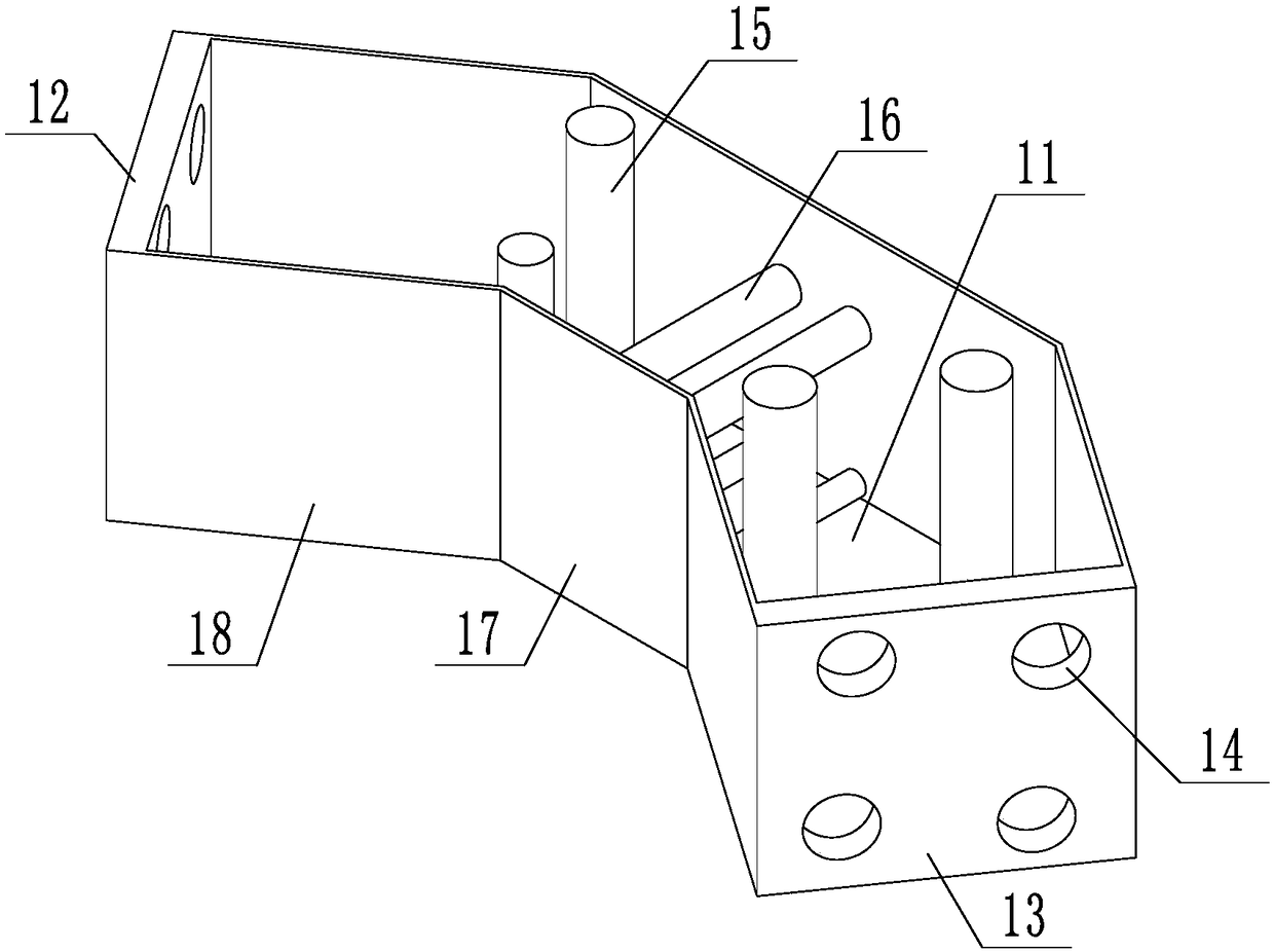
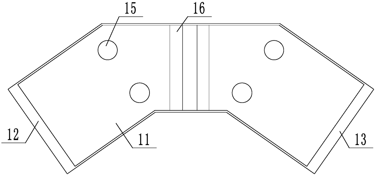
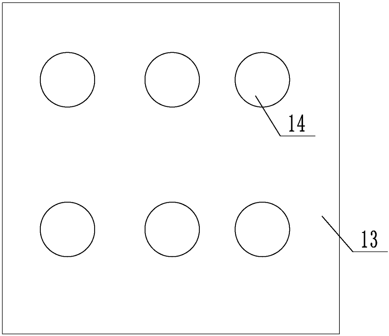
[0029] Such as figure 1 and figure 2 As shown, a cable tray includes a bottom plate 11, and the two ends of the bottom plate 11 are respectively equipped with a first line plate 12 and a second line plate 13, and the first line plate 12 and the second line plate 13 are according to the cable specification and Quantity opens 4-9 cable hole 14, divides two to three layers of layout.

[0030] A plurality of vertical rods 15 are installed on the base plate, and the vertical rods can determine the number of columns of the vertical rods according to the number of rows of the cable holes, for example, if the cable holes are in four rows, then the vertical rods are correspondingly arranged in four rows.

[0031] The vertical rods can be fixed as hangers for fixing the entire bridge frame.

[0032] In the optimal design of the scheme, because the first line plate and the second line plate are under a greater force when pulling the cable, angle irons are installed on both sides of th...


PUM


Abstract

A cable bridge relates to the field of power supply equipment and comprises a bottom plate, wherein a first line plate and a second line plate are respectively arranged at two ends of the bottom plate, a plurality of cable holes are formed in the first line plate and the second line plate according to specifications and numbers of cables, a plurality of vertical rods are arranged on the bottom plate, and the lines of the vertical rods are determined according to the lines of the cable holes. In the device, initial cable laying can be achieved only by the bottom plate, the first line plate, thesecond line plate and the vertical rods, and the device is low in cost; by the device, the construction progress is substantially reduced, a large amount of labor used during the cable laying processis effectively reduced, monitoring can be implemented during the installation process, an original cable slot is prevented, and the cable is very easy to armor and press at a corner to cause damage to the cable or collapse of the bridge.

Description

technical field [0001] The invention relates to the field of power supply equipment, in particular to a cable tray. Background technique [0002] Cable trays are divided into trough type, tray type, ladder type, grid type and other structures, and are composed of brackets, supporting arms and installation accessories. The bridge frame in the building can be erected independently or attached to various buildings (structures) and pipe gallery supports. It should reflect the characteristics of simple structure, beautiful appearance, flexible configuration and convenient maintenance. All parts need to be galvanized. , Installed in the open-air bridge outside the building. [0003] Now the cable tray is prone to many problems when installing and laying cables. The cable tray hanger is applied to the outside of the box plate. When laying cables, it is easy to cause the overall collapse of the bridge frame and cause cable damage; when laying multiple cables, it is easy to cause t...

Claims


Application Information

Patent Timeline
Patent Type & Authority Applications(China)
IPC IPC(8): H02G3/04
CPCH02G3/0406
Inventor 韩伟李勇田广毅赵昌民王斌王文魁高春雨
Owner JINAN CITY CHANGQING DISTRICT POWER SUPPLY CO OF STATE GRID SHANDONG ELECTRIC POWER CO
Learn More