
Underwater acoustic detection device based on photoelectric oscillator

A technology of photoelectric oscillators and detection devices, which is applied to measuring devices, instruments, and measuring ultrasonic/sonic/infrasonic waves. The effect of flexible design and fast demodulation rate

Active Publication Date: 2018-11-02
OCEAN UNIV OF CHINA
View PDF3 Cites 15 Cited by
  • Summary
  • Abstract
  • Description
  • Claims
  • Application Information

AI Technical Summary

Problems solved by technology

However, although fiber laser hydrophone technology has the advantages of simple structure in constructing wavelength division multiplexing arrays, the introduction of gain active optical fiber and pump light makes the structure more complex and increases the difficulty of manufacture.
A large number of fiber lasers are placed at the wet end as sensing elements, making it extremely difficult to guarantee system performance
In addition, the pump absorption problem severely limits the number of sensing elements that can be carried by a single fiber, and the laser resonator coherence collapse problem means that the fiber laser used as a sensor is susceptible to back-reflection laser interference and lacks stability, making large-scale The performance of each primitive in the array is disturbed
At present, in the existing fiber grating hydrophone technology, the high performance index of a single unit and the large multiplexing number of the array cannot be satisfied at the same time, which restricts the development of fiber laser hydrophone technology

Method used


Image

  • Underwater acoustic detection device based on photoelectric oscillator
  • Underwater acoustic detection device based on photoelectric oscillator
  • Underwater acoustic detection device based on photoelectric oscillator

Examples


Embodiment 1

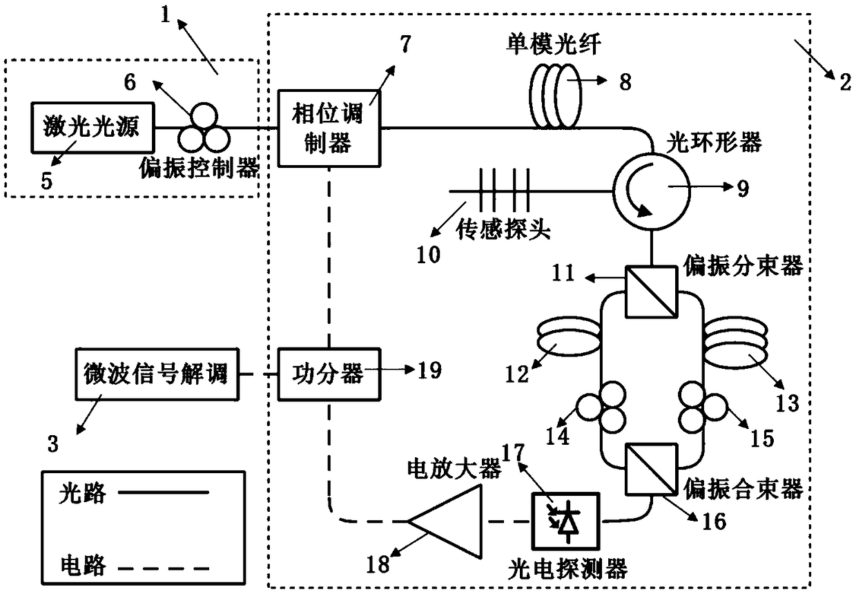
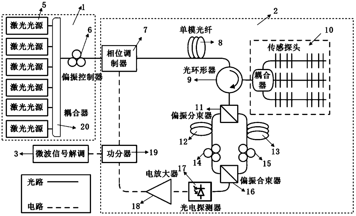
[0041] In order to solve various restrictive problems of the aforementioned fiber grating hydrophone technology, an embodiment of the present invention proposes an underwater acoustic detection device based on a photoelectric oscillator. Among them, the optoelectronic oscillator is an optically generated microwave scheme based on microwave photonics technology, which can generate microwave signals with high Q value, low phase noise and high stability. The photoelectric oscillator is a positive feedback resonant cavity structure composed of a laser source, a phase modulator, an optical fiber, a photodetector, a microwave amplifier, a filter, and a power divider. Its working process is: the laser source generates a continuous Light, modulated by a phase modulator, enters a narrowband fiber grating filter with a special structure, filters out a sideband, and then is converted into an electrical signal by a photodetector; the electrical signal is divided by a power divider after pa...


PUM


Abstract

The invention provides an underwater acoustic detection device based on a photoelectric oscillator. The device comprises a laser light source circuit, a photoelectric oscillation loop and a frequencydemodulation circuit. The device enables a phase-shifted fiber grating or a fiber grating F-P cavity interferometer to be embedded into a microwave photon filter, and uses an elastic cylinder to convert external acoustic wave changes into fiber grating stress or pressure changes, thereby enabling wavelength changes to be converted into the changes in the center frequency of the microwave photon filter, and enabling the frequency of the output microwave signal of the photoelectric oscillator to change. The underwater sound field detection is completed by analyzing the frequency changes by the digital signal demodulation technology. Compared to a conventional fiber optic hydrophone device, the device provided by the invention has higher accuracy, demodulation speed and signal to noise ratio,and a large dynamic range. The technical contents involved mainly include the microwave photon filter making technology, the multi-frequency photoelectric oscillation technology, the scalar sound pressure and three-dimensional sound field measurement technology, the signal demodulation technology, the packaging technology and the array multiplexing technology.

Description

technical field [0001] The invention relates to the technical field of optical fiber underwater acoustic detection, in particular to an underwater acoustic detection device based on a photoelectric oscillator. Background technique [0002] At present, fiber Bragg grating hydrophone technology is mainly divided into ordinary fiber Bragg grating (FBG) type, fiber Bragg grating Fabry-Perot (FBG-FP) cavity type, and fiber laser type. The optical fiber hydrophone technology based on ordinary FBG is a kind of optical fiber underwater acoustic detection technology that was studied earlier, and it is mainly divided into two types: intensity modulation type and interference type. Intensity-modulated FBG hydrophone technology uses excellent tunable lasers or high-precision wavelength scanning devices to convert changes in the central wavelength of reflected light into changes in light intensity. The interferometric FBG hydrophone technology uses the unbalanced interferometer to achie...

Claims


Application Information

Patent Timeline
IPC IPC(8): G01H9/00
CPCG01H9/002G01H9/004
Inventor 尹彬吴松华
Owner OCEAN UNIV OF CHINA
Learn More