
An in-furnace jet flow heating device

A heating device and jet technology, applied to lighting and heating equipment, furnaces, furnace types, etc., can solve the problems of energy saving and environmental protection, uneven heating of workpieces, etc., and achieve the effects of compact structure, improved heating efficiency, and consistent spraying effect

Pending Publication Date: 2018-11-02
海安金锻工业有限公司
View PDF5 Cites 0 Cited by
  • Summary
  • Abstract
  • Description
  • Claims
  • Application Information

AI Technical Summary

Problems solved by technology

In our daily parts production process, parts often need to be heated. With the advancement of technology, jet heating technology has gradually appeared. Jet heating is to spray heated gas with a certain pressure through a nozzle of a certain shape, and directly A method of heating the material surface. The jet heating technology has the advantage of high heating efficiency. The commonly used jet heating equipment is to heat the air in the heating chamber, and the heated hot air is sprayed onto the workpiece through the nozzle. This heating equipment is easy The phenomenon of uneven heating of the workpiece is caused, and the effect of energy saving and environmental protection cannot be achieved, so we need to design a jet device that can heat the workpiece evenly and have the effect of energy saving and environmental protection

Method used

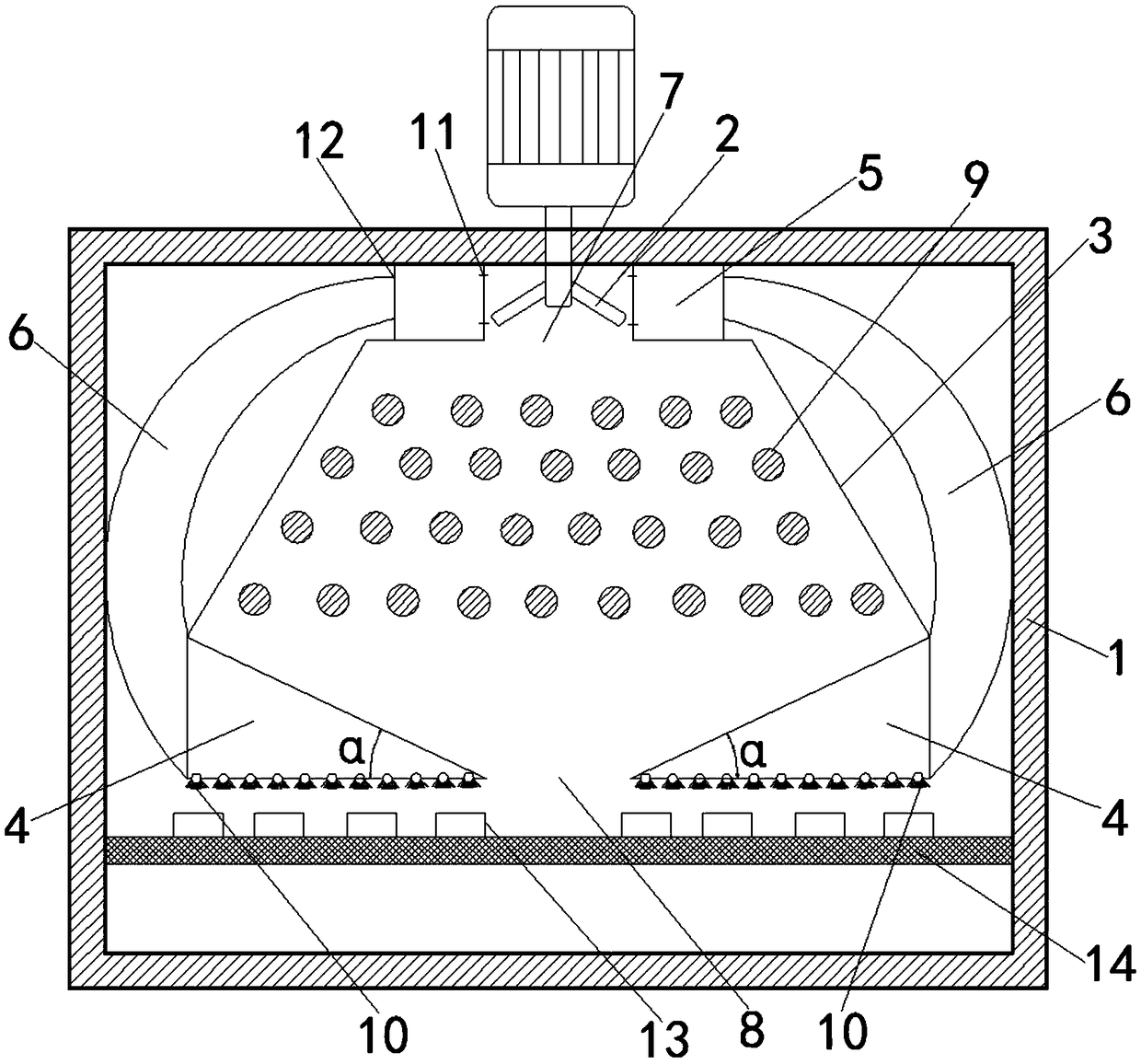

Image

  • An in-furnace jet flow heating device

Examples


Embodiment Construction

[0014] The following will clearly and completely describe the technical solutions in the embodiments of the present invention with reference to the accompanying drawings in the embodiments of the present invention. Obviously, the described embodiments are only some, not all, embodiments of the present invention. Based on the embodiments of the present invention, all other embodiments obtained by persons of ordinary skill in the art without creative efforts fall within the protection scope of the present invention.

[0015] In one embodiment of the present invention, as figure 1 As shown, a jet heating device in a furnace is specifically disclosed, including an induced draft fan 2, a gas heating chamber 3 and a triangular injection chamber 4. Air collection chamber 5, the hot air collection chamber 5 is arranged in the furnace body 1, the gas heating chamber 3 is arranged below the induced draft fan 2, the top of the gas heating chamber 3 is connected with the hot air The bott...


PUM


Abstract

The invention relates to the technical field of heating and specifically discloses an in-furnace jet flow heating device. The device includes an induced draught fan, an air heating cavity, and triangle injection cavities, the induced draught fan is arranged on the top of a furnace, hot-air collection cavities are arranged around the induced draught fan, the hot-air collection cavities are arrangedin the furnace body, the air heating cavity is arranged under the induced draught fan, the top of the air heating cavity clings to the bottom of the hot-air collection cavities, the triangle injection cavities are arranged under the bottom of the air heating cavity, and the hot-air collection cavities communicate with the triangle injection cavities. The range of application of the jet heating device is wide; the hot air generated after heating is sucked by adopting the induced draught fan and enters the triangle injection cavities from the collection cavities through conduction pipes, and the cool air is then sucked again to perform heating, so that repeated cycle utilization is realized, and the resource is saved; heating uniformity of workpieces is guaranteed by adopting the triangle injection cavities, and the heating effect on the workpieces is ensured.

Description

technical field [0001] The invention belongs to the technical field of heating, in particular to a jet flow heating device in a furnace. Background technique [0002] Heating equipment is generally a device consisting of a heating element and accessories. In our daily parts production process, parts often need to be heated. With the advancement of technology, jet heating technology has gradually appeared. Jet heating is to spray heated gas with a certain pressure through a nozzle of a certain shape, and directly A method of heating the material surface. The jet heating technology has the advantage of high heating efficiency. The commonly used jet heating equipment is to heat the air in the heating chamber, and the heated hot air is sprayed onto the workpiece through the nozzle. This heating equipment is easy It causes the workpiece to be heated unevenly, and the effect of energy saving and environmental protection cannot be achieved, so we need to design a jet device that c...

Claims


Application Information

Patent Timeline
Patent Type & Authority Applications(China)
IPC IPC(8): F27B17/00F27D99/00
CPCF27B17/00F27D99/00F27D2099/0065
Inventor 何洪均
Owner 海安金锻工业有限公司
Learn More