An automatic dumping mechanism
A pouring and automatic technology, which is applied in the direction of furnace, furnace type, lighting and heating equipment, etc., can solve the problem that the turning structure of the electric furnace cannot realize fixed-point turning and pouring, and achieve the goal of narrowing the pouring range, shortening the distance, and reducing the production cost Effect
- Summary
- Abstract
- Description
- Claims
- Application Information
AI Technical Summary
Problems solved by technology
Method used
Image

Examples
Embodiment 1
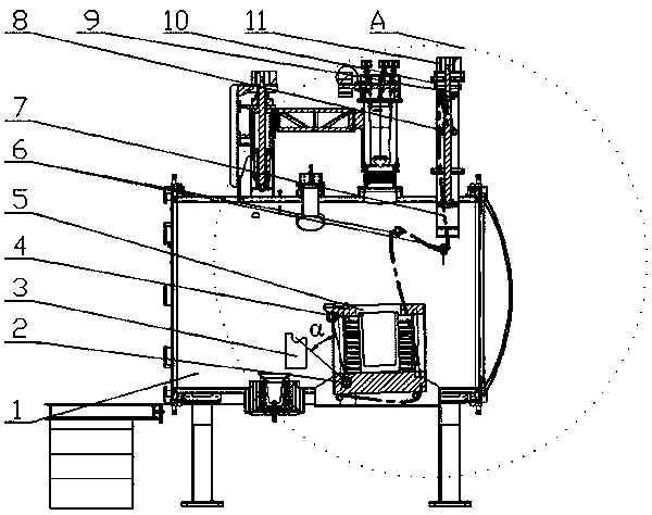
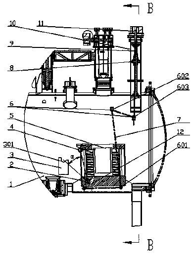
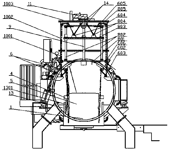
[0035] refer to Figure 1~7: a kind of automatic unloading mechanism of the present embodiment, comprises lower rotating support frame 13, rotating shaft, upper rotating support frame 3, pulley block 6, elevating mechanism 8, drive motor 11 and steel wire rope 7, described elevating mechanism 8 and driving motor 11 connection, which is provided with a reversing pulley 804; one end of the steel wire rope 7 is fixedly connected with the positioning pulley 12 located at the bottom of the melting furnace 5, and then wound around the pulley block 6 and the reversing pulley 804 in turn, and the other end is fixed at the On the positioning pulley 2 14 in the middle of the top plate of the box body 10 above the smelting cylinder 1, the melting furnace 5 is installed in the smelting cylinder 1, and the upper rotating support frame 3 and the lower rotating support frame 13 are provided with fixed rotating Shaft slot 301; the rotating shaft includes a lower rotating shaft 2 and an upper ...
Embodiment 2
[0046] Compared with embodiment 1, a kind of automatic feeding mechanism of this embodiment has the following differences:
[0047] The pulley block 6 consists of a first guide pulley 601 located at the bottom of the melting furnace 5 on the side away from the tundish, a second guide pulley 602, a third guide pulley 603, a fourth guide pulley 604 and a second guide pulley 602 symmetrically distributed on both sides of the melting furnace 5. The fifth guide pulley 605 is composed; the second guide pulley 602 and the third guide pulley 603 are fixed on the inner wall of the upper end of the melting cylinder 1, and the second guide pulley 602 is vertically higher than the third guide pulley 603 , the third guide pulley 603 is slightly higher than the vertical position of the overturned first guide pulley 601; top plate on both sides.
Embodiment 3
[0049] Such as figure 1 As shown, a smelting furnace 5 includes a smelting cylinder 1, a smelting furnace 5 and an automatic dumping mechanism as described in Embodiment 1. Pour into the tundish.
[0050] The working principle and method of use of a kind of automatic feeding mechanism of the present invention are:
[0051] Driving motor 11 drives driving screw mandrel 9 forward rotations, and driving screw mandrel 9 drives guide plate 803 in lifting mechanism 8 to slide down along guide post 802, and steel wire rope 7 moves down with reversing pulley 804 on the guide plate 803, and then is positioned at The length of the wire rope 7 between the positioning pulley 2 14, the fifth guide pulley 605 and the reversing pulley 804 is increased, and the smelting furnace 5 is lifted slowly, and the smelting furnace 5 rotates around the lower rotating shaft 2. Since the smelting furnace 5 has a small inclination angle , the molten metal in it will not fall down; when the length of the...
PUM
 Abstract
Description
Claims
Application Information
 - Generate Ideas
- Intellectual Property
- Life Sciences
- Materials
- Tech Scout
- Unparalleled Data Quality
- Higher Quality Content
- 60% Fewer Hallucinations
Browse by: Latest US Patents, China's latest patents, Technical Efficacy Thesaurus, Application Domain, Technology Topic, Popular Technical Reports.
© 2025 PatSnap. All rights reserved.Legal|Privacy policy|Modern Slavery Act Transparency Statement|Sitemap|About US| Contact US: help@patsnap.com