An orderly automatic movement and fixed-point pouring system of iron mold sand-covered casting

A technology of automatic movement and sand-coating of iron molds, which is applied in foundry workshops, casting equipment, manufacturing tools, etc., can solve the problems of high labor intensity, easy burns for operators, and pollution of pouring sites by manual push boxes, so as to improve production efficiency and Work quality, elimination of molten iron splash card wheel, and the effect of improving the level of automation

Inactive Publication Date: 2016-09-07
BINZHOU HEAD CRANKSHAFT
View PDF7 Cites 0 Cited by
  • Summary
  • Abstract
  • Description
  • Claims
  • Application Information

AI Technical Summary

Problems solved by technology

[0003] Although the first method has a small investment, two products of different materials can enter different tracks for easy pouring, but the manual push box is labor-intensive, and the molten iron splashed during pouring is easy to get stuck on the raceway wheels;
[0004] The second method achieves hydraulic push to reduce labor, but when two products of different materials enter the same row of pouring trolleys, it is difficult to realize the continuous arrangement of the molds of the same bag of molten iron (a dozen boxes), that is to say, when the materials of the two products are different It is impossible to realize the pouring of the same row of pouring trolleys
[0005] At the same time, these two methods are to pour the cast molds one by one by the movement of the crane. The movement of the crane makes the ladle shake, which brings difficulty to pouring, and the splash of molten iron during pouring is not only easy to burn the operator, but also Contaminate the entire pouring site

Method used


Image

  • An orderly automatic movement and fixed-point pouring system of iron mold sand-covered casting
  • An orderly automatic movement and fixed-point pouring system of iron mold sand-covered casting
  • An orderly automatic movement and fixed-point pouring system of iron mold sand-covered casting

Examples


Embodiment Construction

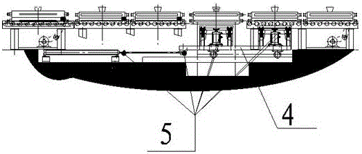
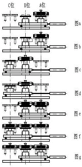
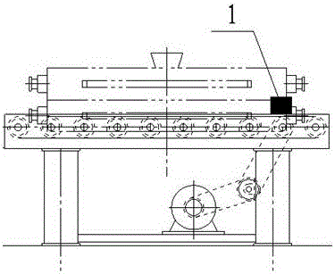
[0016] An iron mold sand-covered casting mold orderly automatic movement and fixed-point pouring system is composed of a photoelectric switch 1, a motorized raceway unit 2, a No. 1 transfer trolley 3, a pouring trolley 4, a proximity switch 5, a No. 1 motorized track 6, Composed of No. 2 motor track 7, No. 2 transfer trolley 8, PLC electrical control cabinet 9, casting cooling track 10, casting exit track 11, No. 3 transfer trolley 12, No. 1 transmission track 13, and No. 2 transmission track 14, its characteristics It is: No. 1 motorized track 6 and No. 2 motorized track 7 are connected by a plurality of motorized raceway units 2, and No. 1 transfer trolley 3 is on the No. 1 transmission track 13, the No. 2 transmission track 14, and the No. 1 motorized track along a specific track. 6 and one end of No. 2 motor track 7, No. 2 transfer car 8 is at the other end of No. 1 motor track 6 and No. 2 motor track 7 along the specific track, and No. 3 transfer car 12 is at No. 1 drive t...


PUM


Abstract

The invention discloses an automatic ordered moving and fixed-point pouring system for sand coated iron mold casting molds, belonging to the field of casting. By installing a plurality of tracks, different types of products can enter corresponding motorized roller ways by virtue of a transfer trolley; a photoelectric switch detects whether the casting molds exist in a front roller way unit, so that automatic operation and ordered arrangement of the casting molds are realized; after reaching the front end of a pouring position, the casting molds are transferred to a pouring bracket without roller ways by virtue of a pouring trolley, and then are poured; after pouring, the poured casting molds are conveyed to automatic roller ways with a detection function to move forwards by virtue of the pouring trolley. Thus, automatic ordered operation and fixed-point pouring of the casting molds are realized; the labor of workers and the mismatch times caused by hitting of the casting molds are reduced, and the situation of wheel blocking caused by splashing of molten iron is eliminated; two products made of different materials can be independently poured; the pouring difficulty is lowered; a small amount of molten iron which is splashed into pits of the sand-coated pouring trolley can be removed regularly, so that an excellent working environment is ensured.

Description

technical field [0001] The invention relates to the field of casting, in particular an iron mold sand-covered casting mold orderly and automatic movement and fixed-point pouring system composed of a pouring trolley, a photoelectric switch, a proximity switch and the like. Background technique [0002] With the continuous development of casting technology, iron mold sand coating technology has been more and more widely used in crankshaft, camshaft and other fields. There are two kinds of layouts of sand-covering lines for iron molds commonly used now: one is that two molding lines correspond to two non-motorized side raceways, and the molds of different products made are manually pushed on them and placed on the corresponding raceways. Pouring; the second is that the two molding lines correspond to one pouring trolley line, and the two types of product molds produced by the two molding lines run on the same row of pouring trolleys, and the operation of the trolleys is driven ...

Claims


Application Information

Patent Timeline
Patent Type & Authority Patents(China)
IPC IPC(8): B22D47/00
Inventor 张之奎尹士文
Owner BINZHOU HEAD CRANKSHAFT
Why Eureka
Try Eureka