Ceramic photo-curing 3D printing system and method

A 3D printing and light curing technology, applied in the field of additive manufacturing in mechanical manufacturing, it can solve the problems of complex process, increased cost, and relatively high requirements for projection resolution, so as to improve the forming rate, prevent slurry precipitation, and ensure reliability. sexual effect

Inactive Publication Date: 2018-11-02
XI AN JIAOTONG UNIV
View PDF7 Cites 8 Cited by
  • Summary
  • Abstract
  • Description
  • Claims
  • Application Information

AI Technical Summary

Problems solved by technology

[0003] However, the forming accuracy of surface exposure light curing technology greatly depends on the projection chip and projection lens used. When printing parts with large structures and relatively simple shapes, projection lenses with high resolution can meet the manufacturing requirements. Small, complex shapes, and parts with small internal holes and thin walls, the requirements for projection resolution are relatively high, and may even reach several microns, that is, low-light curing
Moreover, after a piece of equipment is designed, the resolution of the projection equipment and the projection lens has been determined, so the ability of the printed ceramic parts is also determined. In order to realize the formation of any structure, it is necessary to replace the projection equipment and projection equipment with different resolutions. The projection lens not only increases the cost but also makes the process more complicated

Method used


Image

  • Ceramic photo-curing 3D printing system and method
  • Ceramic photo-curing 3D printing system and method
  • Ceramic photo-curing 3D printing system and method

Examples


Embodiment Construction

[0030] The present invention is described in further detail below in conjunction with accompanying drawing:

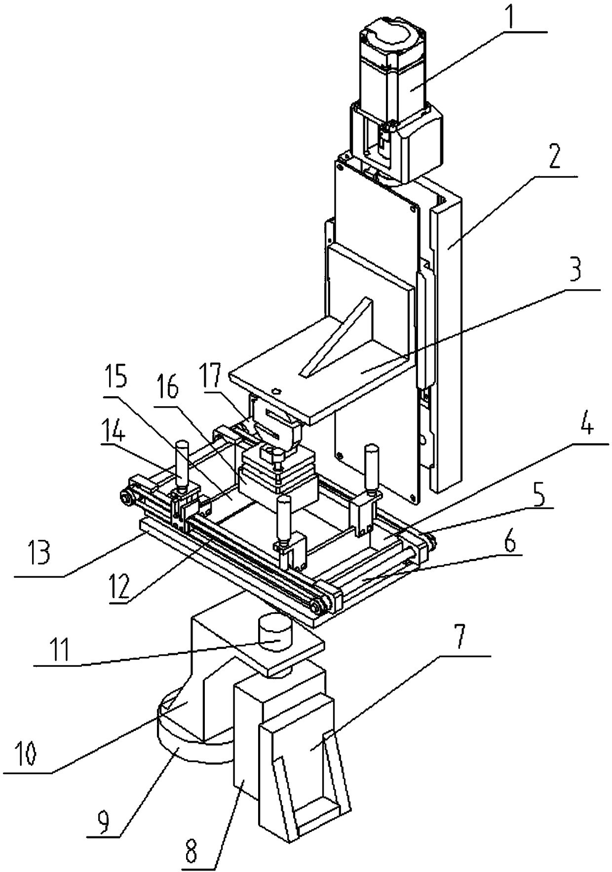
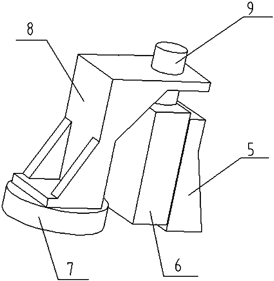
[0031] refer to figure 1 and figure 2 , the ceramic photocuring 3D printing system described in the present invention includes a DLP projection system, a computer, a liquid tank 4, a transparent bottom plate 13, an elastic separation film, a workbench 16, a coating scraper 15 located in the liquid tank 4, and is used to drive The driving device for the coating scraper 15 to move in the liquid tank 4, the liquid supply system for providing the light-cured slurry in the liquid tank 4, and the Z-axis control system for controlling the movement of the workbench 16 in the vertical direction; the liquid The tank 4 is located on the transparent base plate 13, the elastic separation film is located between the transparent base plate 13 and the liquid tank 4, and the workbench 16 is located directly above the liquid tank 4; the DLP projection system includes a DLP projection ...


PUM


Abstract

The invention discloses a ceramic photo-curing 3D printing system and method. The printing system is characterized in that a liquid tank is located on a transparent bottom plate, an elastic separationmembrane is positioned between the transparent bottom plate and the liquid tank, and a working table is located right above the liquid tank; and a DLP projection system comprises a DLP projection mechanism, a fixing frame, a projection lens, a rotating table and a lens converter, wherein the projection lens is located right below the transparent bottom plate, the DLP projection mechanism is fixedon the fixing frame, light emitted by the DLP projection mechanism passes through the projection lens, the transparent bottom plate and the elastic separation membrane and then is irradiated onto light-cured slurry in the liquid tank, the lens converter is fixed on the rotating table, moreover, a fixing plate is arranged on the lens converter, a mounting hole is formed in the fixing plate, and the projection lens is located in the mounting hole. According to the ceramic photo-curing 3D printing system and method, projection equipment with different resolutions and the projection lenses with different resolutions can be relatively conveniently replaced, moreover, the precision of part forming is high, and the quality of the part surface is good.

Description

technical field [0001] The invention belongs to the field of additive manufacturing in mechanical manufacturing, and relates to a ceramic photocuring 3D printing system and method. Background technique [0002] Due to its high forming precision and good surface quality, light-curing 3D printing technology is widely used in rapid prototyping manufacturing technology, and it is also the earliest commercialized technology in 3D printing technology. It mainly uses the light source to selectively irradiate the photopolymerizable slurry according to the pattern of the current layer to cure one layer, and then the workbench moves to the position of the second layer for selective curing. In this way, the cycle is accumulated layer by layer until the entire layer is printed. , to obtain a complete light-cured molded part. Photocuring 3D printing technology currently mainly includes laser scanning photocuring and surface exposure photocuring. Surface exposure photocuring can greatly ...

Claims


Application Information

Patent Timeline
Patent Type & Authority Applications(China)
IPC IPC(8): B28B1/00B33Y30/00
Inventor 连芩刘小栋李涤尘武向权何晓宁孟佳丽曹毅
Owner XI AN JIAOTONG UNIV
Why Eureka
Try Eureka