Rotary striking tool

A tool and rotational force technology, applied in the field of rotary hammering tools, can solve problems such as deterioration of torque accuracy and reduction of beating times, and achieve the effects of suppressing deterioration, suppressing abnormal beating, and efficient fastening operations

Active Publication Date: 2018-11-02
MAKITA CORP
View PDF13 Cites 5 Cited by
  • Summary
  • Abstract
  • Description
  • Claims
  • Application Information

AI Technical Summary

Problems solved by technology

[0012] In this case, the hammer does not hit the anvil, but goes over the anvil, and the number of blows per motor rotation decreases, resulting in abnormal blows that deteriorate the torq...

Method used


Image

  • Rotary striking tool
  • Rotary striking tool
  • Rotary striking tool

Examples


Embodiment Construction

[0051] Embodiments of the present invention will be described below in conjunction with the accompanying drawings.

[0052] In this embodiment, as an example of the rotary driving tool of the present invention, a cordless impact driver 1 for fixing screws such as bolts and nuts to be fastened to an object will be described.

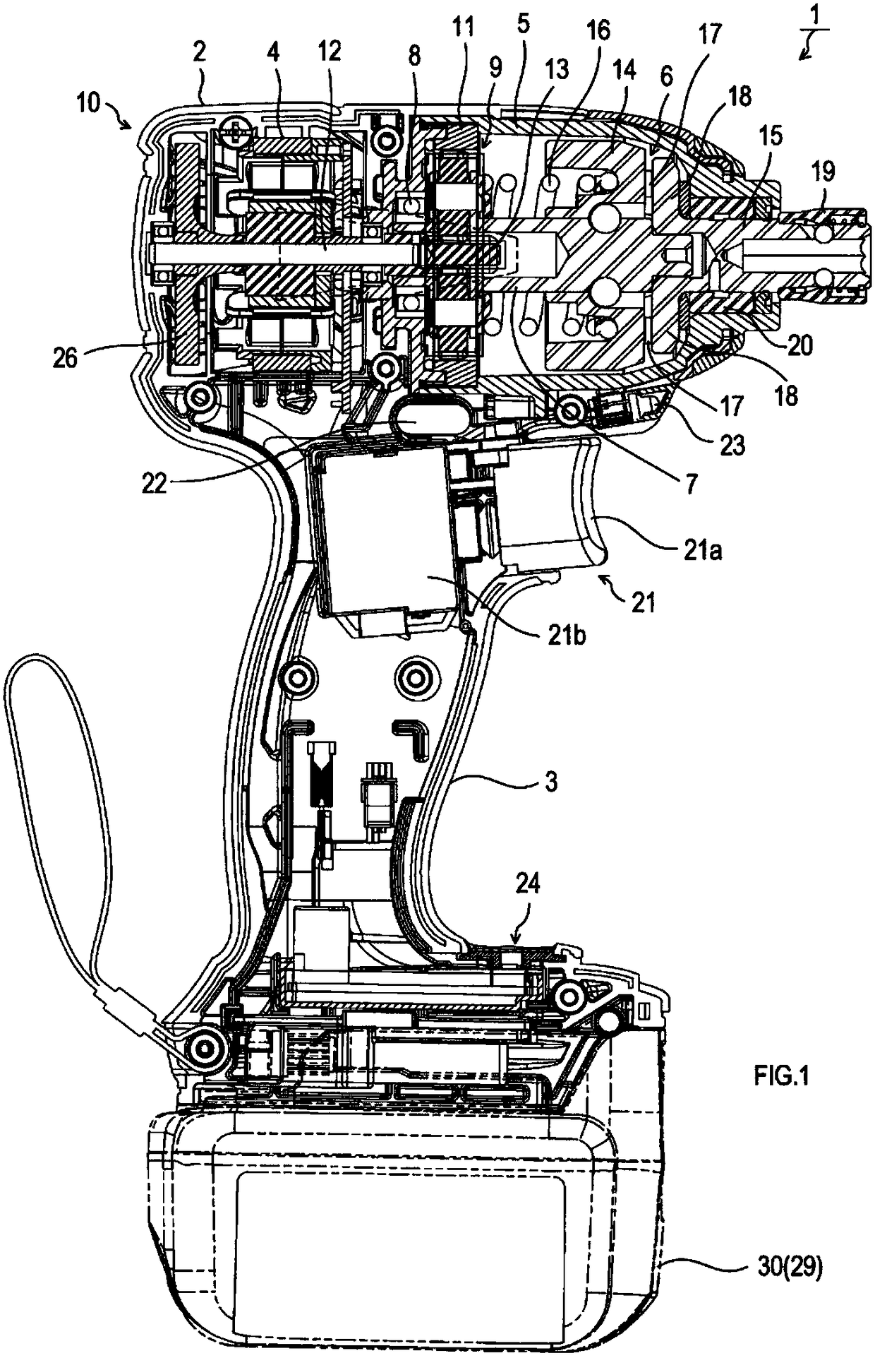
[0053] Such as figure 1 As shown, the cordless impact driver 1 of this embodiment is composed of a tool body 10 and a battery pack 30 that supplies power to the tool body 10 .

[0054] The tool main body 10 is composed of a housing 2 housing a motor 4, a beating mechanism 6, etc. described later, and a lower portion of the housing 2 ( figure 1 The lower side) protrudingly formed handle portion 3 constitutes.

[0055] Inside the housing 2, at its rear ( figure 1 The left side of the motor 4 is housed, and in front of the motor 4 ( figure 1 The right side of the hammer case 5 is assembled with a bell-shaped hammer case 5 , and a striking mechanism 6 is ...


PUM


Abstract

The invention provides a rotary striking tool. A fastening torque is controlled into a rotary striking tool with a desired torque by the constant rotation control of the motor. Before striking, the motor can rotate at a high speed and the abnormal striking is avoided. The rotary striking tool is provided with a motor, a striking mechanism, a striking detection unit, and a control unit. The striking mechanism includes a hammer that is rotated by the rotational force of the motor, an anvil to be rotated by the rotational force of the hammer, and a mounting portion for mounting the tool member onthe anvil. When a torque of more than a predetermined value is applied to the anvil base from the outside, the hammer is separated from the anvil to spin. Meanwhile, the anvil is struck in the rotating direction, and the control unit detects a strike by using the striking detection unit after the driving of the motor is started. At the same time, the PWM (pulse width modulation) control is carried out on the electrifying current flowing to the motor at a constant duty ratio. The rotation speed of the motor is controlled to be constant as a constant rotation speed if the striking detection part is used for detecting the striking.

Description

technical field [0001] The present invention relates to a rotary striking tool, which is rotated by the rotational force of a motor and exerts striking force in the direction of rotation when a torque greater than a predetermined value is applied from the outside. Background technique [0002] Conventionally, a rotary hammering tool includes a hammer that is rotated by the rotational force of a motor, and an anvil that is rotated by the rotational force of the hammer. [0003] Then, when a torque greater than a predetermined value is applied from the outside to the anvil on which the tool member is mounted, the hammer is freed from the anvil and idling, and after idling by a predetermined angle, hits the anvil in the rotational direction. [0004] Therefore, according to the rotary driving tool, when fixing the screw to the target object, the screw can be firmly fastened to the target object by hitting the anvil with the hammer. [0005] In addition, in such a rotary drivin...

Claims


Application Information

Patent Timeline
IPC IPC(8): B25D17/00
CPCB25D17/005B25B21/02B25B23/1475B25B21/008B25F5/001B25B21/026B25B21/023
Inventor 长田高明山本浩克石川刚史嶋邦久
Owner MAKITA CORP
Why Eureka
Try Eureka