
An experimental device for high frequency resistance welding

A technology of high-frequency resistance welding and experimental equipment, which is applied in the direction of resistance welding equipment, welding equipment, manufacturing tools, etc., can solve the problem that the extrusion volume of equipment and experimental equipment without burr extrusion volume control can not be ideally controlled and other issues to achieve the effect of ensuring the safety of life

Active Publication Date: 2020-02-25
江苏诺森特电子科技有限公司
View PDF5 Cites 0 Cited by
  • Summary
  • Abstract
  • Description
  • Claims
  • Application Information

AI Technical Summary

Problems solved by technology

[0002] In the existing experimental devices for controlling the amount of burr extrusion in high-frequency resistance welding, there are great disadvantages. There are few devices for controlling the amount of extrusion, or the control is relatively rigid, and there is no more professional high-frequency resistance welding burr Extrusion amount control equipment, the extrusion amount of the experimental device modified from the original equipment cannot be ideally controlled, and the welding quality is poor, which makes the research experimental data inaccurate and cannot obtain correct research results. The experimental device is more dangerous when it is running, and it will endanger the personal safety of the experimenters in severe cases

Method used


Image

  • An experimental device for high frequency resistance welding
  • An experimental device for high frequency resistance welding
  • An experimental device for high frequency resistance welding

Examples


Embodiment Construction

[0023] Below in conjunction with accompanying drawing and embodiment the present invention will be further described:

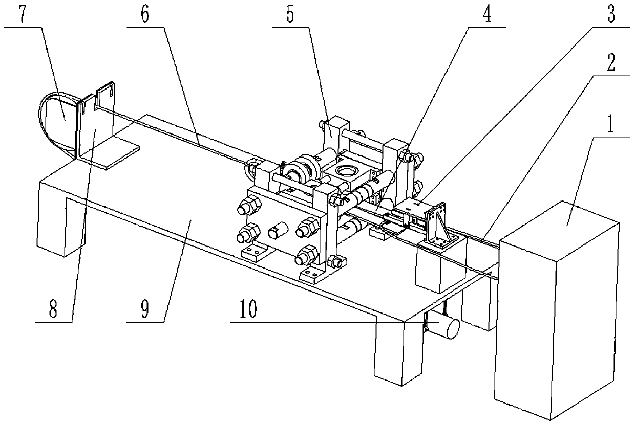
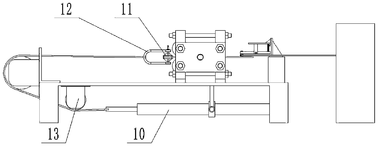
[0024] exist figure 1 with figure 2 In the schematic diagram of the experimental device for high-frequency resistance welding shown, the high-frequency power supply 1 is placed on the ground and connected to the electrode 3.4 of the resistance welding machine 3 through the high-frequency power supply line 2, and the workbench 3.1 of the resistance welding machine is fixed on the machine tool 9 at one end. exist Figure 4-Figure 6 In the shown schematic diagram of the resistance welding machine of the present invention, a support frame 3.2 is fixed on the workbench, a support plate 3.3 parallel to the machine tool is fixed on the support frame, and the upper end of the connecting rod support 3.6 is vertically fixed below the support plate. The lower end of the rod support is connected with the middle part of the connecting rod 3.5 by bolts, and the adjacen...


PUM


Abstract

The invention provides a high-frequency resistance welding experiment device. The high-frequency resistance welding experiment device mainly comprises a machine tool, a resistance welding machine component, a welding rolling mill component and a welding plate material traction component, wherein the machine tool and a high-frequency power source of the resistance welding machine component are botherected on the ground, the high-frequency power source is connected with a resistance welding machine through a high-frequency power source wire, the resistance welding machine is fixed on the machine tool and is in contact with a welding plate material, the welding plate material is placed inside a welding rolling mill, the welding rolling mill is also fixed on the machine tool, a D-shaped shackle connects the welding plate material with a steel wire rope, the steel wire rope spans a large pulley and a small pulley and is attached to hydraulic equipment finally, the large pulley is fixed ona pulley supporting rack, the pulley supporting rack is fixed on the machine tool, the small pulley and the hydraulic equipment are both fixed to the bottom of the machine tool, and the welding speedis controlled by controlling a speed adjusting valve on the hydraulic equipment. The high-frequency resistance welding experiment device can control the squeeze amount of the plate material in high-frequency resistance welding, can also guarantee the personal safety of experimental personnel and has good welding efficiency.

Description

technical field [0001] The invention relates to an experimental device for high-frequency welding. Background technique [0002] In the existing experimental devices for controlling the amount of burr extrusion in high-frequency resistance welding, there are great disadvantages. There are few devices for controlling the amount of extrusion, or the control is relatively rigid, and there is no more professional high-frequency resistance welding burr Extrusion amount control equipment, the extrusion amount of the experimental device modified from the original equipment cannot be ideally controlled, and the welding quality is poor, which makes the research experimental data inaccurate and cannot obtain correct research results. The experimental device is more dangerous when it is running, and it will endanger the personal safety of the experimenters in severe cases. Contents of the invention [0003] The object of the present invention is to provide an experimental device for...

Claims


Application Information

Patent Timeline
Patent Type & Authority Patents(China)
IPC IPC(8): B23P23/00B23K11/00B23K11/36
CPCB23K11/00B23K11/36B23P23/00
Inventor 于恩林张凯范文军
Owner 江苏诺森特电子科技有限公司
Learn More