Copper wire shearing device

A copper wire and wire trimming technology, which is applied in the field of copper wire trimming devices, can solve the problems of increased labor costs and low processing efficiency, and achieve the effects of convenient post-welding, small length error, and reduced space occupation

Pending Publication Date: 2018-10-30
JULI AUTOMATION EQUIP ZHEJIANG CO LTD
View PDF0 Cites 3 Cited by
  • Summary
  • Abstract
  • Description
  • Claims
  • Application Information

AI Technical Summary

Problems solved by technology

Using the existing technology, the flat copper wire can only be cut first, and then the two ends of the copper wire are processed into pointed shapes, which requires additional special processing equipment, low processing efficiency, and increased labor costs

Method used


Image

  • Copper wire shearing device
  • Copper wire shearing device
  • Copper wire shearing device

Examples


Embodiment Construction

[0022] The present invention will be further described now in conjunction with accompanying drawing.

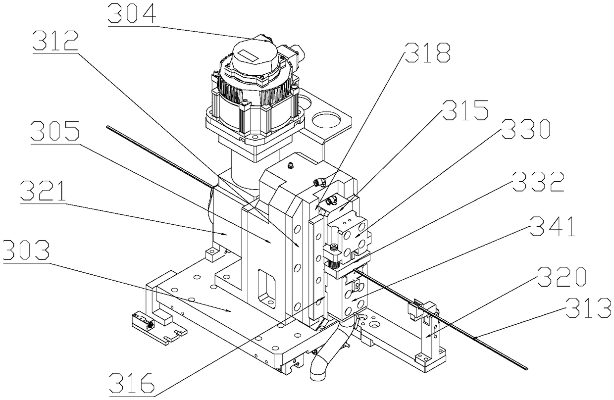
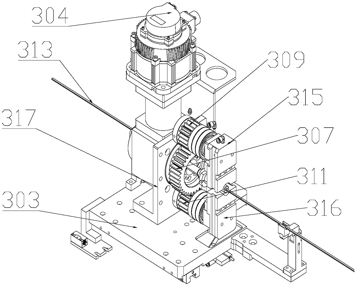
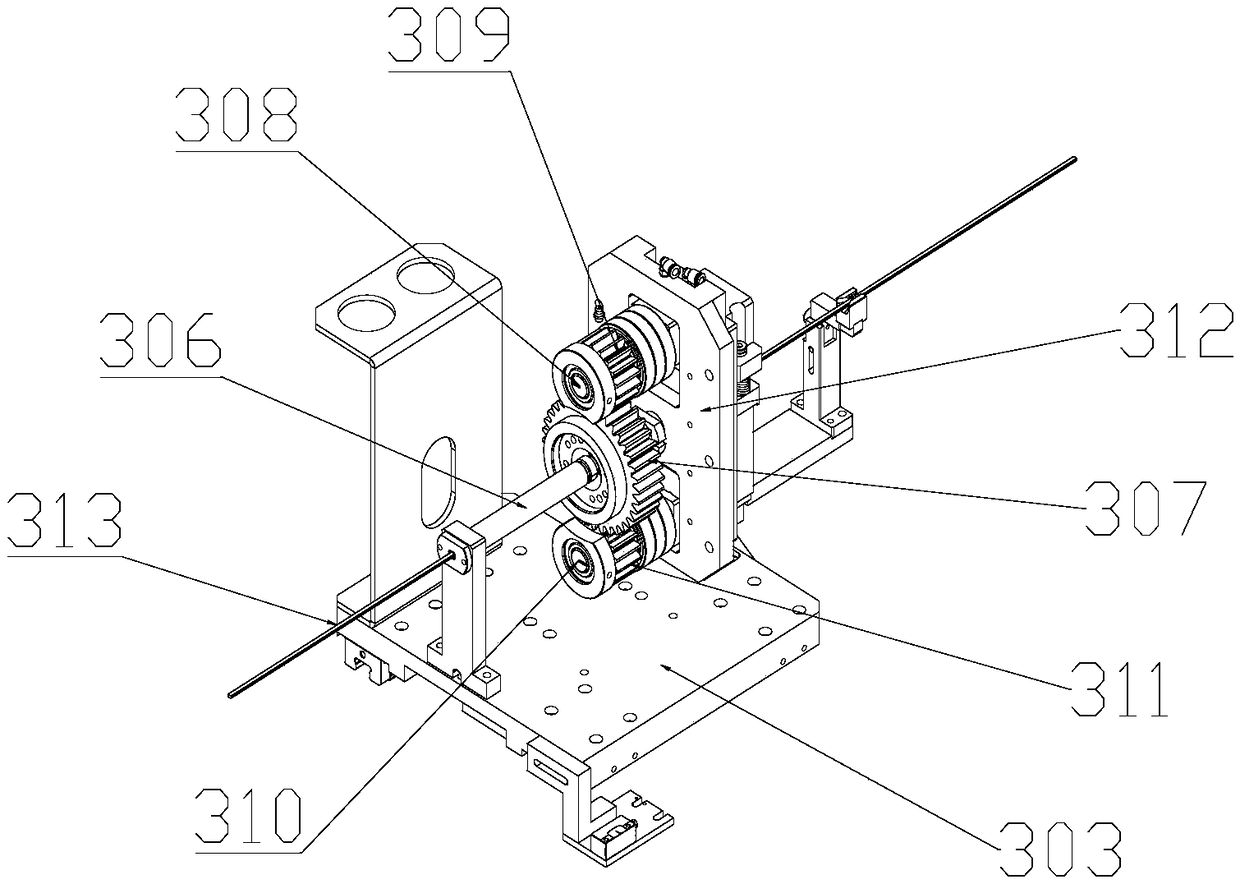
[0023] Such as Figure 1-5 As shown, the copper wire trimming device includes a power mechanism and a scissors mechanism. The power mechanism includes a wire trimming base 303, a power motor 304, and a gear box 305. The gear box 305 is fixed on the wire trimming base 303, and the gear The box 305 is provided with a hollow shaft 306, a middle gear 307 installed on the hollow shaft 306, an upper rotating shaft 308, an upper gear 309 installed on the upper rotating shaft 308, a lower rotating shaft 310, a lower gear 311 installed on the lower rotating shaft 310, the gear Case 305 includes front side plate 317 and rear side plate 312, and the two ends of hollow shaft 306, upper rotating shaft 308 and lower rotating shaft 310 are rotatably installed on the front side plate and rear side plate 312 respectively by bearing, the hollow shaft 306 The two ends respectively expose the g...


PUM


Abstract

The invention discloses a copper wire shearing device. The copper wire shearing device comprises a power mechanism and a scissor mechanism. The copper wire shearing device is characterized in that a power motor drives two eccentric shafts to achieve revolution through a hollow shaft, the two eccentric shafts cooperate with elliptical holes correspondingly, an upper sliding guide block and a lowersliding guide block are driven to move on a vertical sliding rail, so that downward moving of the upper sliding guide block is achieved, and upward moving of the lower sliding guide block is achieved;and a copper wire penetrates through the part between a guide block and a lower die and is located between two guide plates at the same time. According to the copper wire shearing device, an upper shearing body is pressed downwards and a lower shearing body is ejected upwards correspondingly under the drive of the upper sliding guide block and the lower sliding guide block, a pressing head mutually cooperates with a lower pointed edge in a second square hole, the copper wire is sheared into a tip shape, an upwarp part on an upper pointed edge cooperates with an upwarp part in the lower pointed edge, and a pointed part is flattened; and the copper wire with a certain length can be sheared according to needs, the wire shearing efficiency of the copper wire is improved, the length error of the copper wire is small, meanwhile, the two ends of the copper wire are sheared into the required pointed shapes, the pointed ends of the copper wire are flattened, later welding is facilitated, and the occupied space of welding joints is reduced.

Description

technical field [0001] The invention relates to the technical field of copper wire processing, in particular to a copper wire cutting device. Background technique [0002] In the production process of the motors used in new energy vehicles, the stators and rotors of the motors are produced separately, and then assembled to form a complete motor. The winding of the stator of the traditional motor is to wind the copper wire in the stator slot, but for the high-power motor used in the new energy vehicle, etc., the flat copper wire is generally cut into U-shaped connecting wires, and then the U-shaped connecting wires are separated Insert it into the stator slot, and finally weld the connectors of the U-shaped connecting wires separately by a welding machine to form a complete stator winding. The length and shape of the U-shaped connecting wire are specific, so the copper wire needs to be cut into small sections of equal length. Manual wire trimming takes a lot of time for meas...

Claims


Application Information

Patent Timeline
Patent Type & Authority Applications(China)
IPC IPC(8): B21F11/00
CPCB21F11/00
Inventor 章日平廖旺生
Owner JULI AUTOMATION EQUIP ZHEJIANG CO LTD
Why Eureka
Try Eureka