


Quick Research
Generate reliable direction feasibility study reports for your R&D in just a few steps.

Technical Q&A
Discover and master advanced knowledge NOW. Basics, ideas, possibilities, all at once.

Find Solutions
As an expert in R&D theories, this can generate solutions to your technical problems instantly.

Evaluate Feasibility
Analyze your overall solution with one click, know your potential R&D risks in advance.

Monitor Landscape
Get weekly tech updates, stay abreast of the latest tech innovations and key insights.
Thread trimming device on sewing machine and operation method of thread trimming device
A sewing machine and thread trimming technology, applied in the field of thread trimming devices, can solve problems such as low thread trimming efficiency, and achieve the effects of preventing rust and high efficiency
- Summary
- Abstract
- Description
- Claims
- Application Information
AI Technical Summary
Problems solved by technology
Method used
Image

Examples
Embodiment 1
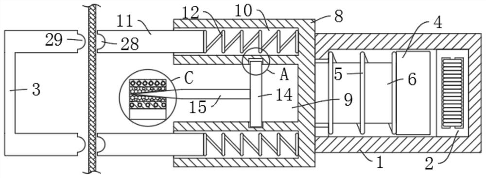
[0037] refer to Figure 1-7 , a thread trimming device on a sewing machine and an operation method thereof, comprising a device box 1 and a C-shaped block 3 fixedly installed on the sewing machine, an electromagnet 2 is fixedly installed on the right side inner wall of the device box 1, and an inner slide of the device box 1 A permanent magnet 4 corresponding to the electromagnet 2 is connected, and the permanent magnet 4 is elastically connected to the left inner wall of the device box 1 by a return spring 5. The left end of the permanent magnet 4 is fixedly connected with a slide bar 6 extending to the outer wall. The left end of 6 is fixedly connected with device block 8, is provided with positioning device between the left side of device block 8 and C-shaped block 3, and the left side of device block 8 is provided with device groove 9, is connected with and connected with by reciprocating mechanism in device groove 9. The blade 15 corresponding to the 3 grooves of the C-sh...
Embodiment 2
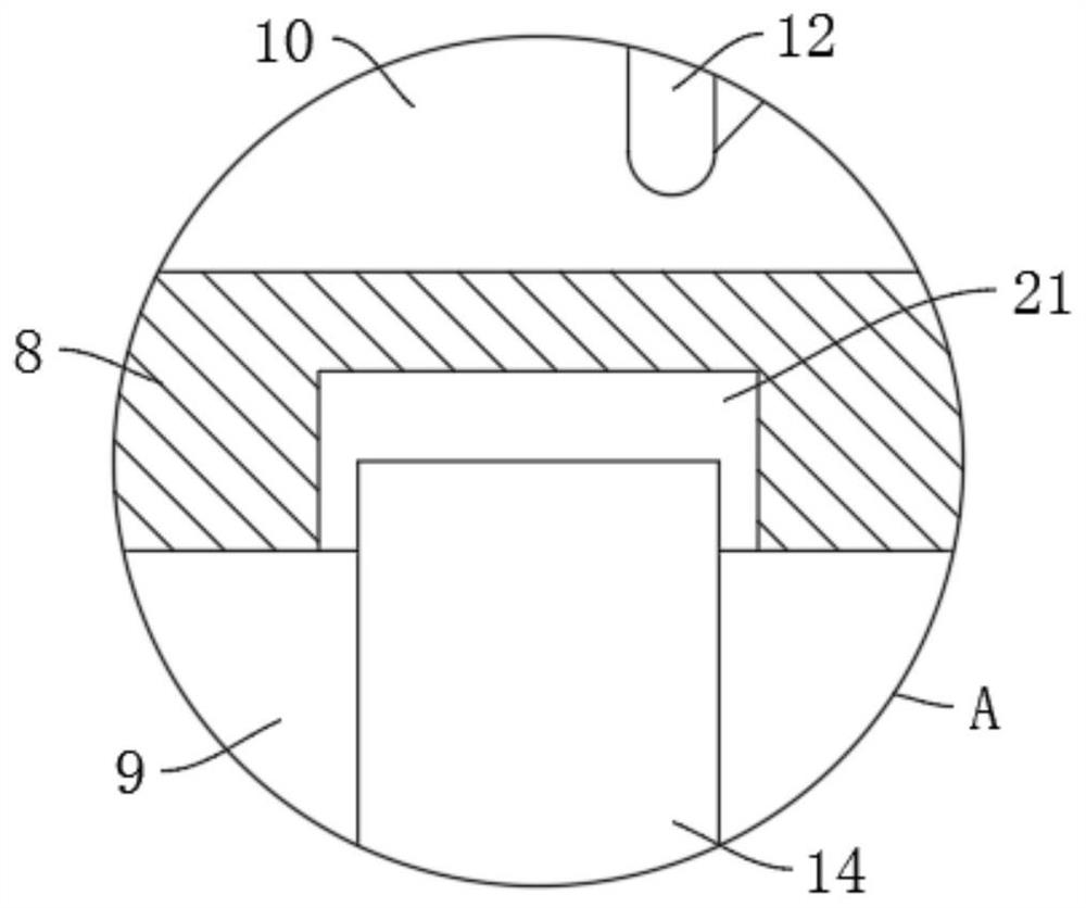
[0039] refer to figure 1, is basically the same as Embodiment 1, furthermore: the positioning device includes two slideways 10 arranged on the left side of the device block 8, and the top pressure plate corresponding to the right end of the C-shaped block 3 is slidably connected in the two slideways 10 11. The top pressure plate 11 and the inner wall of the slideway 10 are elastically connected by the top pressure spring 12, the permanent magnet 4 will drive the device block 8 to slide to the left through the slide bar 6, and the device block 8 will drive the two top pressure plates on the left side wall 11 is pressed against the right side wall of the C-shaped block 3, so as to fix the upper and lower ends of the line segment between the two top pressure plates 11 and the C-shaped block 3. At this time, when the end line is cut, the line is easier to cut under stress .
[0040] Furthermore, the left ends of the two top pressure plates 11 are provided with a semicircular groo...
Embodiment 3
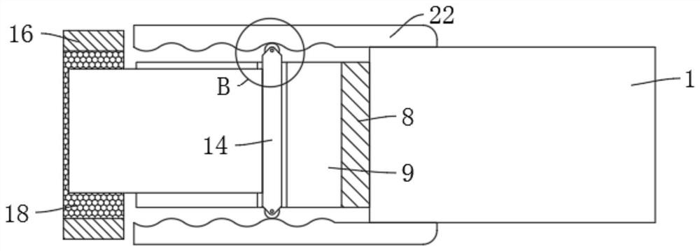
[0042] refer to Figure 1-4 , is basically the same as Embodiment 1, furthermore: the reciprocating mechanism includes chute 21 arranged on the upper and lower side walls of the device groove 9, the two chute 21 are slidingly connected to the mounting plate 14, and the blade 15 is fixedly installed on the mounting plate 14 Side walls, the front and rear side walls of the device box 1 are all fixedly connected with a wave linear plate 22, and the front and rear side walls of the mounting plate 14 are all slidably connected to the side walls of the wave linear plate 22. After the line is fixed, the device block 8 continues to the left At this time, the pressing plate 11 will overcome the pressing spring 12 and retract into the slideway 10, while the blade 15 slides in the direction of the thread and cuts the thread. Sliding back and forth makes it easier for the blade 15 to cut off the wire segment, even if the blade 15 becomes blunt, the wire can be cut off, so that the wire cu...
PUM
 Abstract
Description
Claims
Application Information
 - R&D Engineer
- R&D Manager
- IP Professional
- Industry Leading Data Capabilities
- Powerful AI technology
- Patent DNA Extraction
Browse by: Latest US Patents, China's latest patents, Technical Efficacy Thesaurus, Application Domain, Technology Topic, Popular Technical Reports.
© 2024 PatSnap. All rights reserved.Legal|Privacy policy|Modern Slavery Act Transparency Statement|Sitemap|About US| Contact US: help@patsnap.com