
Intelligent wearable equipment

A smart wearable device and component technology, applied in the field of smart wearables, can solve the problems of high heat dissipation cost and poor heat dissipation performance, and achieve the effect of optimizing heat dissipation and heat dissipation performance

Pending Publication Date: 2018-10-26
GUANGDONG XIAOTIANCAI TECH CO LTD
View PDF5 Cites 2 Cited by
  • Summary
  • Abstract
  • Description
  • Claims
  • Application Information

AI Technical Summary

Problems solved by technology

[0003] The purpose of the present invention is to provide a smart wearable device to solve the problems of poor heat dissipation performance and high heat dissipation cost of existing smart wearable devices

Method used


Image

  • Intelligent wearable equipment
  • Intelligent wearable equipment
  • Intelligent wearable equipment

Examples


Embodiment 1

[0032] This embodiment provides a smart wearable device, including:

[0033] shell;

[0034] PCBA components are arranged in the shell;

[0035] Battery: located at the bottom of the casing, the battery is located under the PCBA assembly;

[0036] Display module: set on the top of the housing, and the display module is located above the PCBA assembly.

Embodiment 2

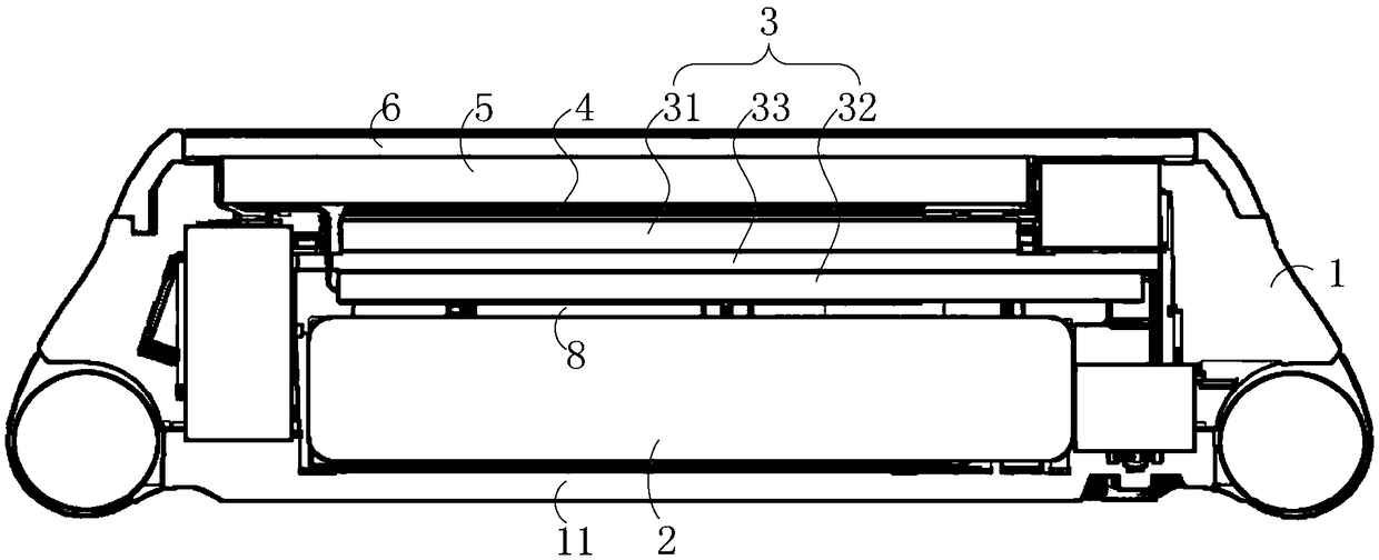
[0038] This embodiment provides a smart wearable device, specifically a smart watch, such as figure 1 As shown, the smart watch includes a casing 1 and a battery 2 , a PCBA assembly 3 , a thermal paste 4 , a display module 5 and a touch screen cover 6 stacked inside the casing 1 from bottom to top.

[0039] Specifically, the battery 2 is disposed on the bottom 11 of the housing 1 , and the battery 2 is fixed to the bottom 11 of the housing 1 by battery adhesive. combine figure 2 As shown, the outer periphery of the battery 2 is wrapped with a composite conductive cloth 7, and the composite conductive cloth 7 includes a conductive cloth located on the outer layer and graphite located on the inner layer of the conductive cloth, and the composite conductive cloth material is formed by the conductive cloth and the graphite. Wrapping the composite conductive cloth 7 around the periphery of the battery 2 can realize uniform heat dissipation of the battery.

[0040] Specifically, ...

Embodiment 3

[0046] The difference between this embodiment and the second embodiment is that in this embodiment, the low-power device is arranged in the second shielding cover above the PCB, and the second shielding cover with the low-power device is located below the display module. That is, both the low-power device and the high-power device are arranged above the PCB board, thereby further ensuring that the main heat source is far away from the bottom of the casing.


PUM


Abstract

The invention relates to the technical field of intelligent wearing, in particular to intelligent wearable equipment. The intelligent wearable equipment comprises a shell, a PCBA assembly, a battery and a display screen module, wherein the PCBA assembly is arranged in the shell, the battery is arranged at the bottom of the shell and is arranged blew the PCBA assembly, and the display screen moduleis arranged at the top of the shell and is arranged above the PCBA assembly. By the intelligent wearable equipment, the heat dissipation performance of the intelligent wearable equipment can be optimized.

Description

technical field [0001] The invention relates to the technical field of smart wearables, in particular to a smart wearable device. Background technique [0002] In the existing 4G smart wearable devices, the motherboard generates a lot of heat, and the heat will be quickly transferred to the bottom case, resulting in an excessively high temperature of the bottom case. When the user wears a smart wearable device for high-power operations such as calls or videos, the overheating of the bottom case will be more obvious. On the one hand, since the bottom shell directly contacts the human body, the temperature of the bottom shell will be directly transmitted to the human skin. If the temperature is too high, it may easily burn the skin or affect the wearing comfort; on the other hand, the overheated smart wearable device cannot dissipate the heat in time. It is easy to cause problems such as crash or slow function response. If you want to solve the problems such as overheating o...

Claims


Application Information

Patent Timeline
Patent Type & Authority Applications(China)
IPC IPC(8): H05K7/20G04G17/04G04G17/02
CPCH05K7/2039H05K7/205G04G17/02G04G17/04
Inventor 黄智永
Owner GUANGDONG XIAOTIANCAI TECH CO LTD
Learn More