Optical microfluidic composite pipe channel
A composite tube type and microfluidic technology, which is applied in the direction of laboratory containers, coatings, chemical instruments and methods, etc., can solve the problems of contact pollution, cumbersome processing, high cost, etc., and achieve a wide range of applications and reduce costs , Ease of recycling
Active Publication Date: 2018-10-26
PEKING UNIV
View PDF6 Cites 2 Cited by
- Summary
- Abstract
- Description
- Claims
- Application Information
AI Technical Summary
Problems solved by technology
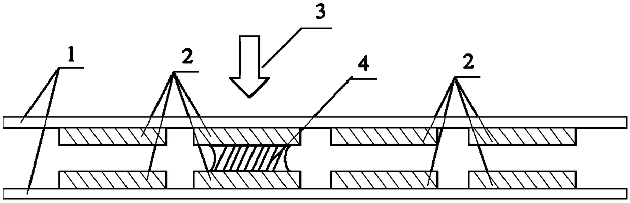
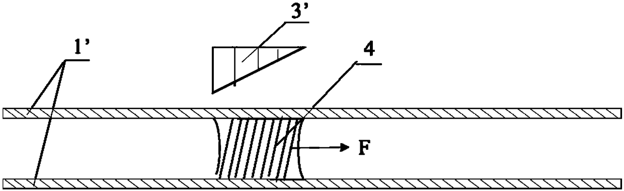
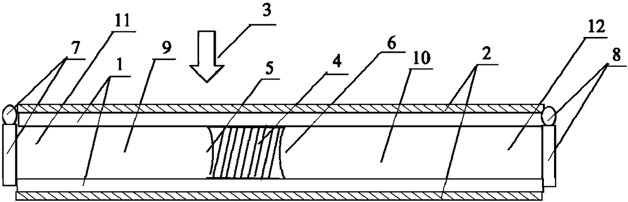
[0008] In order to solve the problems of contact pollution, high cost, cumbersome processing, etc., the optical-microfluidic composite tubular channel provided by the present invention includes a transparent and flexible micro-pipe, which is characterized in that the outer surface of the micro-pipe has a photoresponsive coating, The photoresponsive coating has a photothermal effect and a photoexpansion effect under the action of light in a specific wavelength range; the micropipe has at least one liquid inlet and one liquid outlet, and has a seal at the liquid inlet and the liquid outlet respectively. valve
Method used
View moreImage
Smart ImageViewing Examples

Examples
specific Embodiment
[0044] Specific example form:
[0045]
Login to View More PUM
| Property | Measurement | Unit |
|---|---|---|
| thickness | aaaaa | aaaaa |
| thickness | aaaaa | aaaaa |
Abstract
The invention discloses an optical microfluidic composite pipe channel. The optical microfluidic composite pipe channel comprises a transparent flexible micro-pipe. The outer surface of the micro-pipeis provided with a photoresponse coating. The photoresponse coating has the photothermal effect and the photo-induced expansion effect under the effect of light within a specific wavelength range. The micro-pipe is provided with at least one liquid flow-in port and a liquid flow-out port. Each of the liquid flow-in port and the liquid flow-out port is provided with a sealing valve. The provided optical microfluidic composite pipe channel does not pollute transmitted liquid, is cheap in coating, energy-saving and efficient, and capable of combining the microfluidic effects of photomechanical drive and photothermal drive, and flexibly realizing the coarse adjustment and the fine adjustment of a microfluidic position.
Description
technical field [0001] The invention relates to a flexible channel for optically controlled fluid transmission, which belongs to the field of optically controlled fluid material technology and related devices. Background technique [0002] Microfluidic technology is a technology that uses microtubes to control tiny fluids. It is suitable for the miniaturization of biochemical experiments, so it is also called lab-on-a-chip. Because of its remarkable efficiency, it is widely used in biomedicine, organic synthesis, chemical analysis and microreactors. The field has a good application prospect. At present, the main application principles are mechanical drive and non-mechanical drive. Mechanical drives mainly include pneumatic drives, piezoelectric drives, and centrifugal drives. The limitation is that the control accuracy cannot meet the higher requirements. Non-mechanical drives mainly include electroosmotic drive, thermal gas drive and light harvesting drive. Among them, el...
Claims
Login to View More Application Information
Patent Timeline
 Patent Type & Authority Applications(China)
IPC IPC(8): B01L3/00C09D7/63C09D7/65
CPCB01L3/5027B01L2300/0832B01L2300/12B01L2300/168C08K5/23C08K5/3435C08L33/14C09D7/63C09D7/65
Inventor 于海峰吕宣德王文忠
Owner PEKING UNIV
Features
- R&D
- Intellectual Property
- Life Sciences
- Materials
- Tech Scout
- Unparalleled Data Quality
- Higher Quality Content
- 60% Fewer Hallucinations
Learn More Browse by: Latest US Patents, China's latest patents, Technical Efficacy Thesaurus, Application Domain, Technology Topic, Popular Technical Reports.
© 2025 PatSnap. All rights reserved.Legal|Privacy policy|Modern Slavery Act Transparency Statement|Sitemap|About US| Contact US: help@patsnap.com