Multifunctional soil crushing equipment
A soil crushing, multi-functional technology, applied in the restoration of polluted soil, shovel, plow and other directions, can solve the problems of low work efficiency, reduced water and soil water retention capacity, time-consuming and labor-intensive, etc., and achieves the effect of convenient operation and reasonable design.
- Summary
- Abstract
- Description
- Claims
- Application Information
AI Technical Summary
Problems solved by technology
Method used
Image
Examples
Embodiment 1
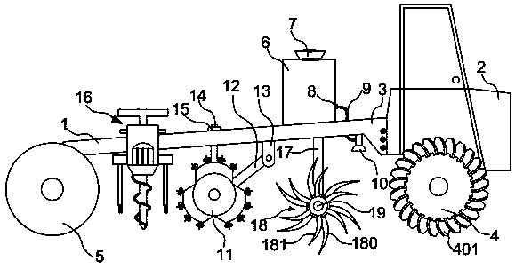
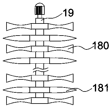
[0025] like Figure 1-2 As shown, the multi-functional soil crushing equipment includes a frame 1, the front end of the frame 1 is connected with a driving device 2 through a traction plate 3, the rear end of the frame 1 is provided with a drive wheel 5, and the bottom surface of the frame 1 is provided with a frame along the length of the frame 1. The loosening device 11 that direction is arranged side by side and can roll, and the front of the loosening device 11 is provided with reclamation mechanism 18, and reclamation mechanism 18 is connected to frame 1 bottom surface by vertical bar 17, and reclamation mechanism 18 comprises the rotating shaft 19 driven by motor, and rotating shaft 19 Digging blades 180 for excavating soil and soil-breaking blades 181 for breaking soil are uniformly arranged in a staggered manner. When the driving device 2 drives the equipment forward, the side reclamation mechanism 18 in front of the loosening device 11 operates, and the rotating shaft ...
Embodiment 2
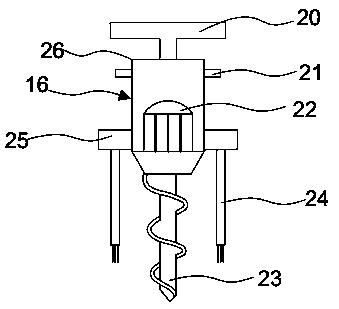
[0027] like figure 1 , 3As shown, the optimization scheme of this embodiment on the basis of Embodiment 1 is: the lower part of the driving device 2 is provided with a roller 4, and the roller 4 is evenly distributed with hobbing teeth 401, and the roller 4 is driven to roll the soil layer by driving the driving wheel 5 to rotate. , the hobbing teeth 401 on the drum 4 penetrate into the soil layer to loosen the soil first. Preferably, the hobbing teeth 401 are arranged obliquely, which is conducive to more even and thorough loosening of the soil layer. The humidity detector 16 on the frame 1, the humidity detector 16 comprises a body 26 and a handle 20 located on the top of the body 26, the bottom of the body 26 is provided with a drill bit 23, the inside of the body 26 is provided with a motor 22 for driving the drill bit 23, and the body 26 Both sides of the exterior are provided with sensor probes 24 fixedly connected by connecting rods 25. The motor 22 inside the body 26 ...
Embodiment 3
[0029] like figure 1 , 5 , 6, the optimization scheme of this embodiment on the basis of Embodiment 1 is: the loosening device 11 moves through the support rod 14 to pass through the frame 1 and is connected with a locking bolt 15. When the loosening device 11 is working, the The locking bolt 15, the support rod 14 descends to drive the loosening device 11 down, so that the loosening device 11 is lower than the drum 4 and the driving wheel 5, and then the loosening device 11 contacts with the soil, starts to work, and when the work is finished, mobilize the locking bolt 15. The rise of the support rod 14 drives the loosening device 11 to rise, so that the loosening device 11 is higher than the drum 4 and the driving wheel 5, thereby protecting the loosening device 11 from ground friction and increasing the service life of the loosening device 11. 11 includes symmetrically arranged steel discs 111, a rotating shaft that can drive the steel discs 111 to rotate is arranged betwe...
PUM
 Abstract
Description
Claims
Application Information
 - R&D
- Intellectual Property
- Life Sciences
- Materials
- Tech Scout
- Unparalleled Data Quality
- Higher Quality Content
- 60% Fewer Hallucinations
Browse by: Latest US Patents, China's latest patents, Technical Efficacy Thesaurus, Application Domain, Technology Topic, Popular Technical Reports.
© 2025 PatSnap. All rights reserved.Legal|Privacy policy|Modern Slavery Act Transparency Statement|Sitemap|About US| Contact US: help@patsnap.com


