Coaxial connector of cable

A coaxial connector and cable technology, which is applied in the direction of connection, two-part connection device, and parts of the connection device, can solve the problems of mutual interference of high-frequency signals, many extension structures, and large standing waves. The effect of increasing connection reliability, simple terminal structure, and reducing thickness

Pending Publication Date: 2018-10-23
LINKCONN ELECTRONICS
View PDF1 Cites 0 Cited by
  • Summary
  • Abstract
  • Description
  • Claims
  • Application Information

AI Technical Summary

Problems solved by technology

Since the wire harness is clamped between the large plane of the conductive terminal and the spring wall of the terminal, the overall thickness of the connector is increased, which is not conducive to the development of thinner connectors, and there are many extension structures on both sides of the terminal, and the middle of the terminal is pressed. The wires are easy to loose and the contact surface with the terminal is relatively large, high-frequency signals will interfere with each other and have a great impact on the standing wave

Method used


Image

  • Coaxial connector of cable
  • Coaxial connector of cable
  • Coaxial connector of cable

Examples


Embodiment Construction

[0034] The present invention will be further described below in conjunction with the accompanying drawings and embodiments.

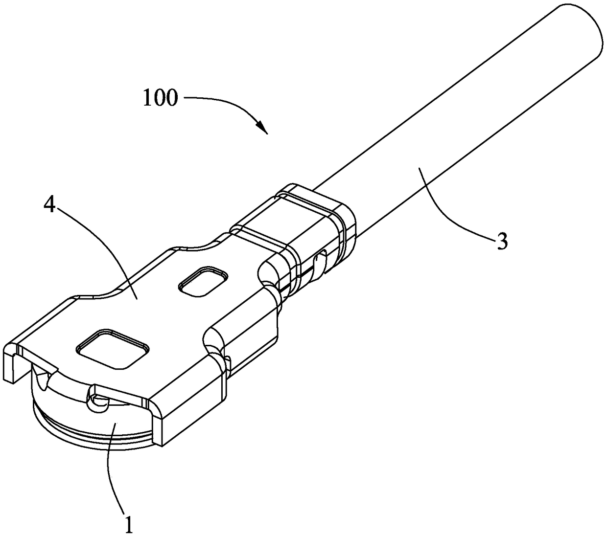
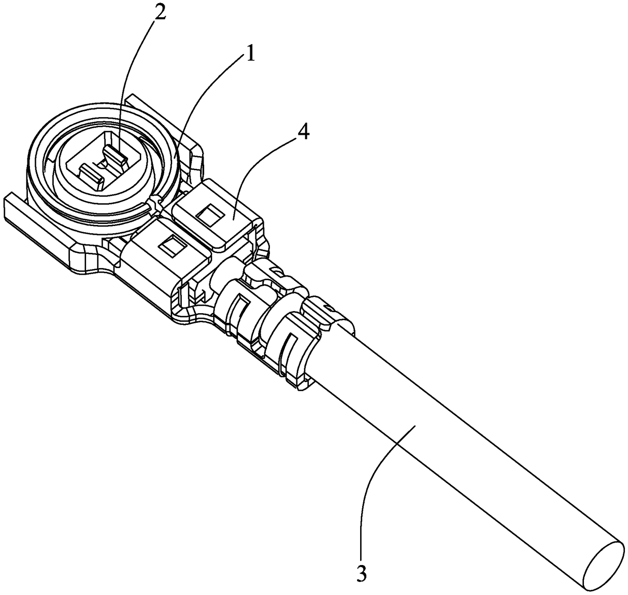
[0035] Such as Figure 1 to Figure 11 As shown, a cable coaxial connector 100 includes: an insulating body 1 , a conductive terminal 2 fixed to the insulating body 1 , a cable 3 connected to the conductive terminal 2 , and a metal shell 4 covering the insulating body 1 .

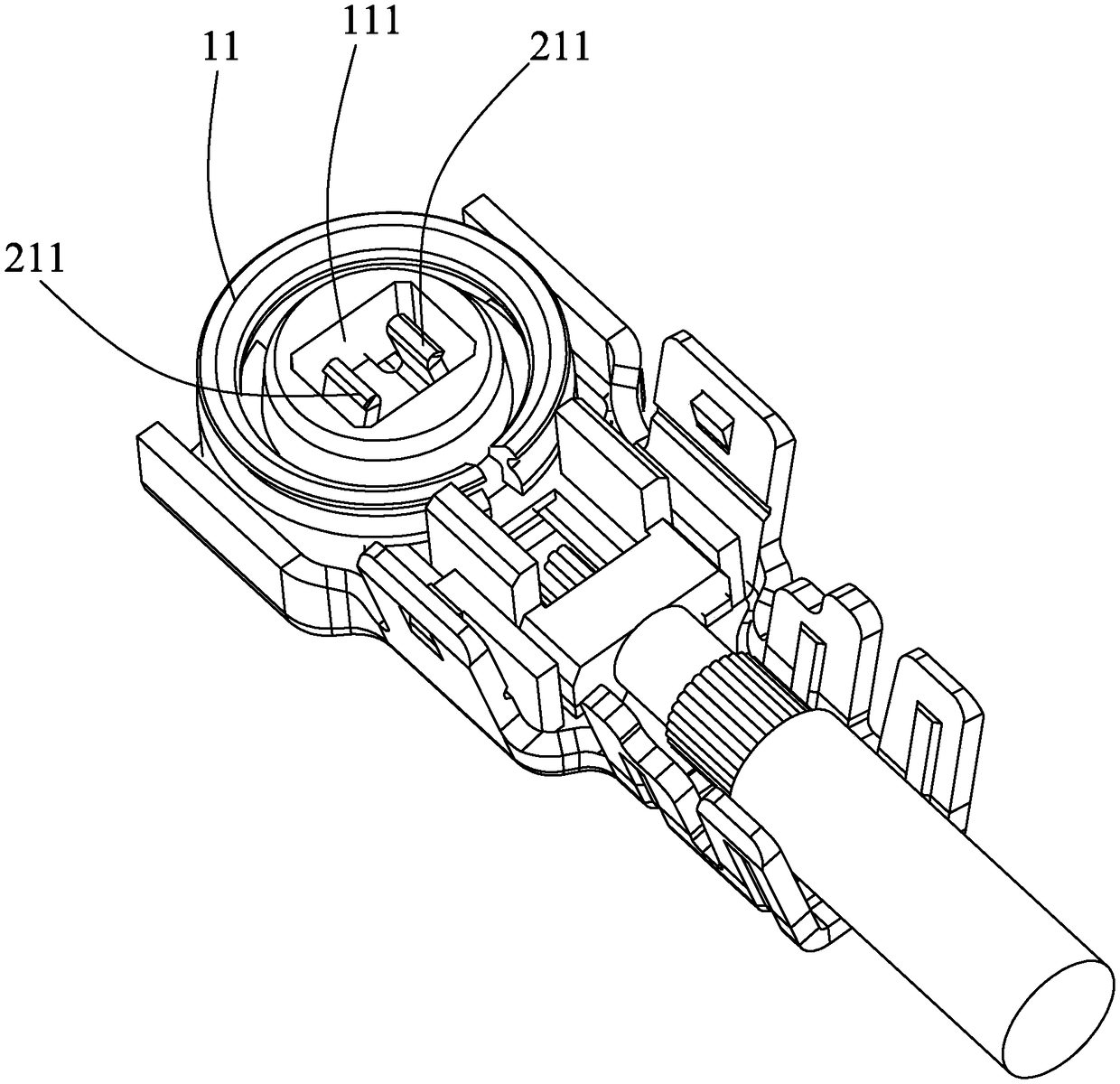
[0036] The insulating body 1 includes a cylindrical portion 11 , a rotatable cover 12 extending upward from a front end of the cylindrical portion 11 , and an extension portion 13 extending backward from a rear end of the cylindrical portion 11 . The cylindrical part 11 is provided with a slot 111 for inserting a mating connector, and the extension part 13 is provided with a receiving groove 131 for receiving the cable 3 . The slot 111 is located on the lower side of the insulating body 1 , the receiving groove 131 is located on the upper side of the insulating body 1 , and the insul...


PUM


Abstract

The invention discloses a coaxial connector of a cable. The connector comprises an insulation body, a conductive terminal fixed to the insulation body, and a cable connected to the conductive terminal. The conductive terminal consists of a connecting plate portion, a butt-joint portion protruding from the connecting plate portion into a plugging slot of a cylindrical portion, and a pressing portion being connected to one end of the connecting plate portion and being accommodated into an accommodation slot of an extension portion; and the pressing portion and a cover plate are arranged at the two ends of the plugging slot. A metal housing is arranged at the outer side of the cover plate; and the cover plate extrudes the pressing portion downwardly to be in contact with the cable. The cableis clamped between the pressing portion and the insulation body, thereby reducing the thickness of the connector and promoting the thinning development of the connector; and the contact area between the cable and the conductive terminal is small and the contact is reliable and the structure between the cable contact portion and the plate end contact portion of the conductive terminal is single without many branches, so that no excessive interference and losses are caused for the high-frequency signal and the standing wave ratio is high.

Description

technical field [0001] The invention relates to a cable coaxial connector, in particular to a cable coaxial connector in the communication field. Background technique [0002] Connectors are widely used in electronic equipment, such as cable coaxial connectors in the communication field. Usually, one end of the cable is connected to the coaxial connector, and the other end is connected to other electronic devices to facilitate signal transmission between the two. , the electrical connection between the cable and the connector, in order to prevent the cable from detaching from the coaxial connector, the connector is usually clamped to the cable, but the connection method in the prior art increases the thickness of the cable and the connector, which is not It is beneficial to the miniaturization development of the coaxial connector. [0003] For the prior art related to the present invention, please refer to the Chinese patent application No. CN104934743A published on July 17...

Claims


Application Information

Patent Timeline
IPC IPC(8): H01R13/40H01R13/502H01R13/629H01R24/38
CPCH01R13/40H01R13/502H01R13/629H01R24/38
Inventor 闻豪阮军
Owner LINKCONN ELECTRONICS
Why Eureka
Try Eureka