
Drying machine for chemical use

A drying machine and chemical technology, applied in the direction of drying machine, drying gas arrangement, drying, etc., can solve the problems of unstable air temperature at the outlet of the evaporator, low oil-water separation efficiency, complicated installation, etc., and achieve good oil-water separation effect , Simple and convenient installation, good stability effect

Inactive Publication Date: 2018-10-23
常州市飞腾工业自动化技术有限公司
View PDF0 Cites 0 Cited by
  • Summary
  • Abstract
  • Description
  • Claims
  • Application Information

AI Technical Summary

Problems solved by technology

[0002] With the rapid development of the current society, various mechanical processing equipment emerge in endlessly, in a variety of ways. In terms of chemical mechanical processing equipment, dryers are a relatively common mechanical processing equipment. At present, most of the chemical mechanical processing equipment for drying machines, The moisture in the material is vaporized and escaped by heating to obtain a solid material with a specified moisture content. Generally, it is divided into two types according to the pressure: normal pressure dryer and vacuum dryer, but the size is too large and the installation is complicated. Problems occur, the air temperature at the outlet of the evaporator is not stable, and the oil-water separation efficiency is low, etc.

Method used


Image

  • Drying machine for chemical use
  • Drying machine for chemical use

Examples


Embodiment Construction

[0017] The following will clearly and completely describe the technical solutions in the embodiments of the present invention with reference to the accompanying drawings in the embodiments of the present invention. Obviously, the described embodiments are only some, not all, embodiments of the present invention. Based on the embodiments of the present invention, all other embodiments obtained by persons of ordinary skill in the art without making creative efforts belong to the protection scope of the present invention.

[0018] In the description of the present invention, it should be noted that the terms "center", "upper", "lower", "left", "right", "vertical", "horizontal", "inner", "outer" etc. indicate The orientation or positional relationship is based on the orientation or positional relationship shown in the drawings, and is only for the convenience of describing the present invention and simplifying the description, rather than indicating or implying that the referred de...


PUM


Abstract

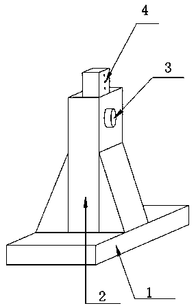
The invention discloses a drying machine for chemical use. A control panel is arranged on the upper side of a motor; a display is arranged on the right side of the control panel; an induced draft fanis arranged on the right side of the motor; bases are arranged on the right side of the induced draft fan; supporting columns are arranged on the upper sides of the bases; fixing devices are arrangedon the upper sides of the supporting columns; a valve is arranged on the upper side of one fixing device; a material tank is arranged on the left side of the valve; a feed inlet is formed in the rightside of the valve; a pulse dust collector is arranged on the lower side of the feed inlet; a reaction tank is arranged on the right side of the pulse dust collector; an air seal device is arranged onthe lower side of the pulse dust collector; a discharge outlet is formed in the lower side of the air seal device; an air compression pipe is arranged on the right side of the reaction tank; an air compressor is arranged on the right side of the air compression pipe; an air blower is arranged on the lower side of the air compressor; and an air filter is arranged on the right side of the air blower. The drying machine for chemical use is convenient to install and has the sealing function to a certain extent, and the dehumidifying effect is achieved by changing the air pressure.

Description

[0001] The invention relates to the technical field of chemical mechanical processing equipment, in particular to a chemical dryer. Background technique [0002] With the rapid development of the current society, various mechanical processing equipment emerge in endlessly, in a variety of ways. In terms of chemical mechanical processing equipment, dryers are a relatively common mechanical processing equipment. At present, most of the chemical mechanical processing equipment for drying machines, The moisture in the material is vaporized and escaped by heating to obtain a solid material with a specified moisture content. Generally, it is divided into two types according to the pressure: normal pressure dryer and vacuum dryer, but the size is too large and the installation is complicated. Problems occur, the air temperature at the outlet of the evaporator is not stable, and the oil-water separation efficiency is low and other common problems. Contents of the invention [0003] ...

Claims


Application Information

Patent Timeline
IPC IPC(8): F26B17/10F26B21/00
CPCF26B17/10F26B21/003F26B21/004
Inventor 孙欣
Owner 常州市飞腾工业自动化技术有限公司
Learn More