
Fool-proofing method for UV laser decapping of PCB

A kind of PCB board, foolproof technology, used in laser welding equipment, electrical components, printed circuit manufacturing and other directions, can solve problems such as circuit board damage, and achieve the effect of preventing damage problems

Inactive Publication Date: 2018-10-19
GUANGZHOU MEADVILLE ELECTRONICS
View PDF6 Cites 1 Cited by
  • Summary
  • Abstract
  • Description
  • Claims
  • Application Information

AI Technical Summary

Problems solved by technology

[0003] In order to overcome the deficiencies of the prior art, the object of the present invention is to provide a fool-proof method for laser uncapping of PCBs, which can solve the problem of circuit board damage caused by repeated cutting

Method used


Image

  • Fool-proofing method for UV laser decapping of PCB
  • Fool-proofing method for UV laser decapping of PCB

Examples


Embodiment Construction

[0020] The technical solutions in the embodiments of the present invention will be clearly and completely described below in conjunction with the accompanying drawings in the embodiments of the present invention. Obviously, the described embodiments are only some of the embodiments of the present invention, not all of them. Based on the embodiments of the present invention, all other embodiments obtained by persons of ordinary skill in the art without making creative efforts belong to the protection scope of the present invention.

[0021] It should be noted that when a component is said to be "fixed" to another component, it can be directly on the other component or there can also be an intervening component. When a component is said to be "connected" to another component, it may be directly connected to the other component or there may be intervening components at the same time. When a component is said to be "set on" another component, it may be set directly on the other co...


PUM


Abstract

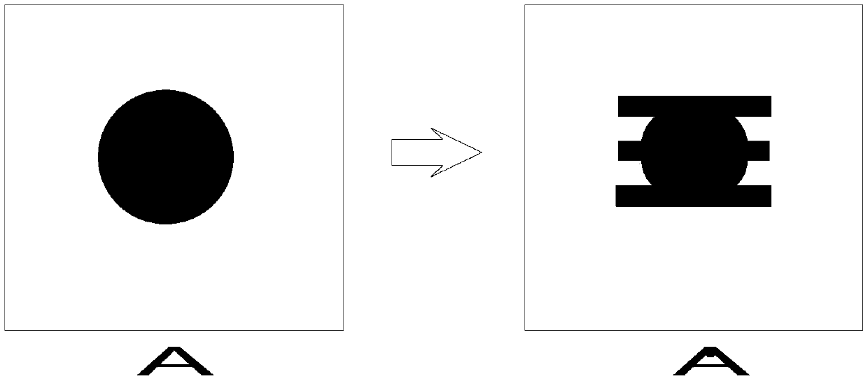
The invention discloses a fool-proofing method for UV laser decapping of a PCB. The method comprises the steps of setting a positioning target, adding a fool-proofing target, adding a cutting position, setting fool-proofing target cutting parameters, grabbing a fool-proofing target and performing cutting stopping and alarming. Through setting the fool-proofing target, in decapping, after all targets are burndown, a laser machine cannot grab the target, and a problem of PCB damage caused by repeated cutting is prevented.

Description

technical field [0001] The invention relates to the field of circuit boards, in particular to a fool-proof method for UV laser cover opening of PCBs. Background technique [0002] At present, the circuit board-PCB (abbreviation for Printed Circuit Board) covers a variety of processes, one of which is to use UV laser (ultraviolet laser) to open the cover after cutting. After cutting the position, it is processed (the purpose is to cut through the unnecessary hard board layer, so that it will not produce defects such as tearing and delamination when peeling off the cover). However, since there is no obvious cutting mark on the cutting position on the board, when using the above process, the PCB board is easy to be cut on the machine again after cutting, then the laser will burn deeply and cause the board to burn deep / burn out and be scrapped. Contents of the invention [0003] In order to overcome the deficiencies of the prior art, the object of the present invention is to ...

Claims


Application Information

Patent Timeline
IPC IPC(8): H05K3/00B23K26/38B23K26/70
CPCB23K26/38B23K26/702H05K3/00
Inventor 张榕晨黄大维陈建军
Owner GUANGZHOU MEADVILLE ELECTRONICS
Learn More