Clock synchronization method based on delay measurement
A technology of clock synchronization and link delay, which is applied in the field of electronics and communication, can solve the problems of inability to achieve synchronization accuracy and different time signal delays, and achieve the effect of reliable time synchronization scheme, high synchronization accuracy and guaranteed accuracy
- Summary
- Abstract
- Description
- Claims
- Application Information
AI Technical Summary
Problems solved by technology
Method used
Image
Examples
Embodiment 1
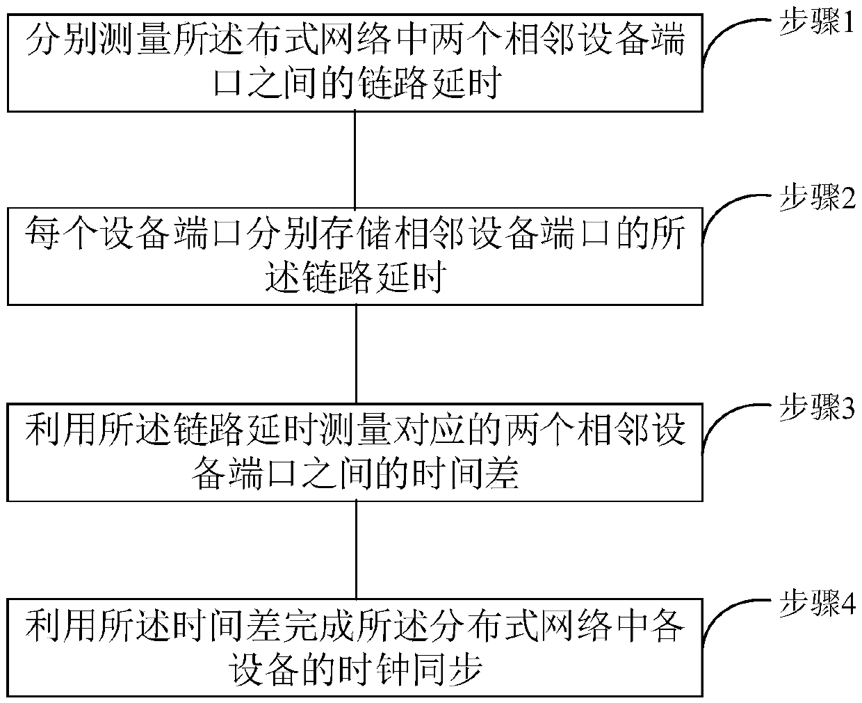
[0059] See figure 1 , figure 1 It is a flow chart of a clock synchronization method based on delay measurement provided by an embodiment of the present invention. The clock synchronization method of the present invention can be used for clock synchronization. Specifically, the method includes the following steps:
[0060] Step 1, respectively measuring the link delay between two adjacent equipment ports in the distributed network;
[0061]Step 2, each device port stores the link delay of the adjacent device port respectively;
[0062] Step 3, using the link delay to measure the time difference between corresponding two adjacent device ports;
[0063] Step 4. Using the time difference to complete the clock synchronization of each device in the distributed network.
[0064] Among them, before step 1, it may also include:
[0065] Step X1, the two adjacent devices send and receive announcement messages to each other;
[0066] Step X2, comparing clock information according to...
Embodiment 2
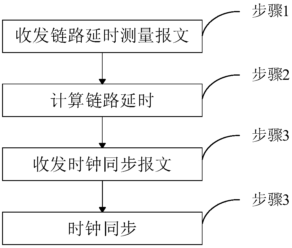
[0106] See figure 2 , figure 2 It is a schematic flowchart of an implementation of a clock synchronization method based on delay measurement provided by an embodiment of the present invention. This embodiment further describes the clock synchronization method in detail on the basis of the foregoing embodiments. Specifically, the following steps are included:
[0107] Step 1. Send and receive link delay measurement messages
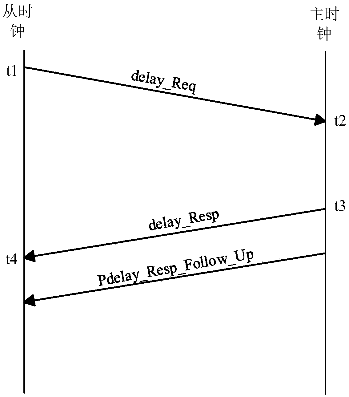
[0108] Such as image 3 As shown, the connected devices are the first device and the second device respectively, the device where the master clock is located is the first device, and the device where the slave clock is located is the second device. Time measurement, the slave clock is the initiator of the delay measurement, and the master and slave devices obtain relevant information by sending messages. The message is the data unit exchanged and transmitted in the network, that is, the data block to be sent by the site at one time. The message conta...
Embodiment 3
[0131] Please continue to see image 3 and Figure 4 , image 3 It is a schematic diagram of the principle of measuring link delay of a clock synchronization method based on delay measurement provided by the embodiment of the present invention; Figure 4 It is a schematic diagram of the principle of measuring time difference in a distributed network clock synchronization method provided by an embodiment of the present invention. This embodiment describes the clock synchronization method in detail on the basis of the foregoing embodiments.
[0132] A distributed network is formed by the interconnection of node machines distributed in different locations and having multiple terminals. Any point in the network is connected to at least two lines. When any line fails, the communication can be completed through other links, which has high reliability. At the same time, the network is easy to expand.
[0133] Preferably, all nodes in the distributed network constitute a clock syn...
PUM
 Abstract
Description
Claims
Application Information
 - R&D
- Intellectual Property
- Life Sciences
- Materials
- Tech Scout
- Unparalleled Data Quality
- Higher Quality Content
- 60% Fewer Hallucinations
Browse by: Latest US Patents, China's latest patents, Technical Efficacy Thesaurus, Application Domain, Technology Topic, Popular Technical Reports.
© 2025 PatSnap. All rights reserved.Legal|Privacy policy|Modern Slavery Act Transparency Statement|Sitemap|About US| Contact US: help@patsnap.com


