Distributed network clock synchronization system
A distributed network, clock synchronization technology, applied in the field of electronics and communication, can solve the problem of unable to achieve clock synchronization accuracy, and achieve the effect of reliable time synchronization scheme and strong robustness
- Summary
- Abstract
- Description
- Claims
- Application Information
AI Technical Summary
Problems solved by technology
Method used
Image
Examples
Embodiment 1
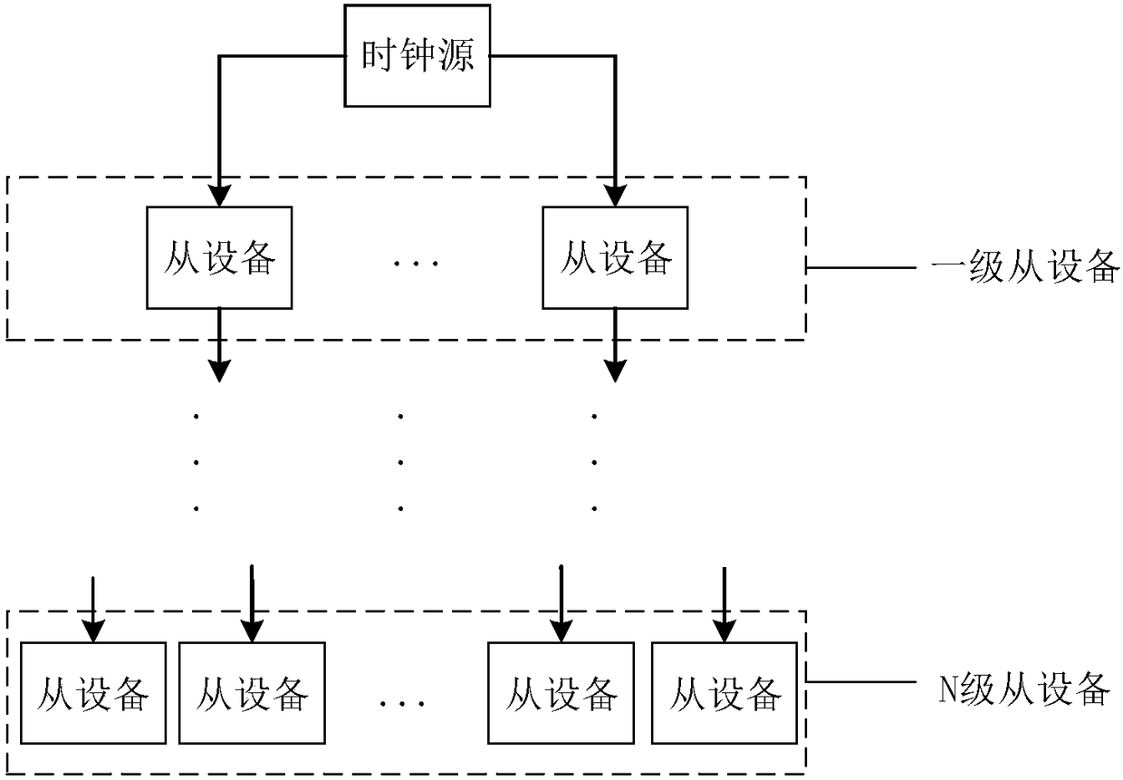
[0043] See figure 1 with figure 2 , figure 1 A schematic structural diagram of a distributed network clock synchronization system provided by an embodiment of the present invention; figure 2 It is a schematic structural diagram of a slave device of a distributed network clock synchronization system provided by an embodiment of the present invention. A distributed network clock synchronization system, comprising:
[0044] Clock source, used to send clock synchronization information;
[0045] At least one level of slave equipment is connected to the clock source step by step, and is used to receive the clock synchronization information step by step and complete clock synchronization; wherein,
[0046] Both the clock source and the at least one slave device are nodes in a distributed network clock synchronization system.
[0047] Preferably, the slave device includes: an interface module, a link delay module, a time difference module, and a synchronization module; wherein ...
Embodiment 2
[0071] Please continue to see figure 1 with figure 2 , figure 1 A schematic structural diagram of a distributed network clock synchronization system provided by an embodiment of the present invention; figure 2 It is a schematic structural diagram of a slave device of a distributed network clock synchronization system provided by an embodiment of the present invention. This embodiment further describes the clock synchronization system in detail on the basis of the foregoing embodiments. The distributed network is formed by the interconnection of nodes distributed in different locations with multiple terminals, which has high reliability and is easy to expand. A distributed network clock synchronization system, such as figure 1 As shown, N is a natural number greater than or equal to 1, and the distributed network clock synchronization system includes a clock source and at least one level of slave equipment, wherein the clock source is used to send clock synchronization in...
Embodiment 3
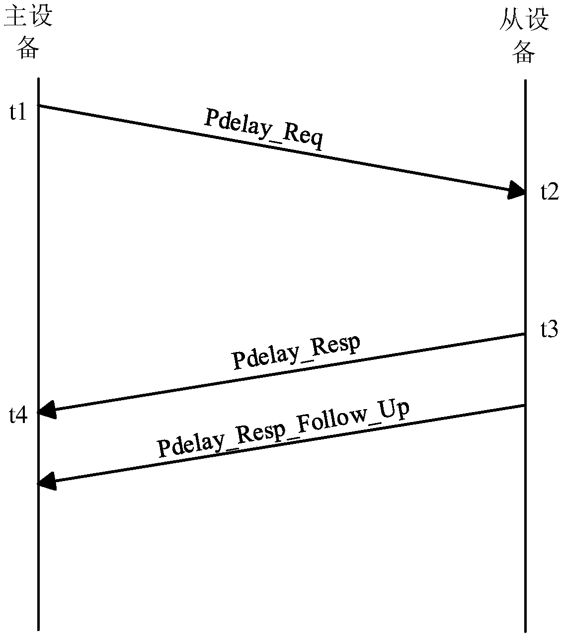
[0082] Please continue to see image 3 with Figure 4 , image 3 A schematic diagram of the delay measurement principle of a distributed network clock synchronization system provided by an embodiment of the present invention; Figure 4 It is a schematic diagram of a time difference principle of a distributed network clock synchronization system provided by an embodiment of the present invention. This embodiment describes the time awareness module and its time synchronization system in detail on the basis of the above embodiments.
[0083] A distributed network is formed by the interconnection of node machines distributed in different locations and having multiple terminals. Any point in the network is connected to at least two lines. When any line fails, the communication can be completed through other links, which has high reliability. At the same time, the network is easy to expand.
[0084] Preferably, all nodes in the distributed network constitute a clock synchronizat...
PUM
 Abstract
Description
Claims
Application Information
 - R&D
- Intellectual Property
- Life Sciences
- Materials
- Tech Scout
- Unparalleled Data Quality
- Higher Quality Content
- 60% Fewer Hallucinations
Browse by: Latest US Patents, China's latest patents, Technical Efficacy Thesaurus, Application Domain, Technology Topic, Popular Technical Reports.
© 2025 PatSnap. All rights reserved.Legal|Privacy policy|Modern Slavery Act Transparency Statement|Sitemap|About US| Contact US: help@patsnap.com


