EMC Cable Glands

A compatible, cable lock technology, applied in conductive connection, clamping/spring connection, connection, etc., can solve the problems that copper terminals cannot be quickly passed through, cannot be quickly grounded, and cable shielding installation is troublesome, saving man-hours , easy to plug, good shielding effect

Active Publication Date: 2020-12-15
JIAXING SHENG YANG ELECTRIC CO LTD
View PDF7 Cites 0 Cited by
  • Summary
  • Abstract
  • Description
  • Claims
  • Application Information

AI Technical Summary

Problems solved by technology

[0004] 1. The copper terminal connected to the cable cannot pass through quickly, and cannot achieve quick grounding;
[0005] 2. The installation of cable shielding is troublesome, and the shielding performance is not good;
[0006] 3. The installation is not easy, and the shielding layer needs to be cut, which consumes man-hours;

Method used


Image

  • EMC Cable Glands
  • EMC Cable Glands

Examples


Embodiment Construction

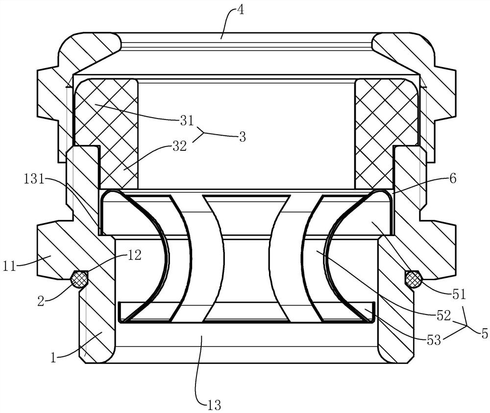
[0020] pass Figure 1 to Figure 2 The electromagnetic compatible cable locking joint of the present invention will be further described.

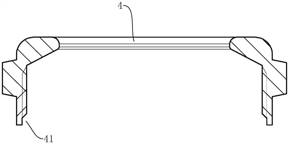
[0021] An electromagnetic compatible cable locking joint, comprising a joint body 1 , a joint cap 4 , a sealing ring 3 and a shield 5 .

[0022] The joint main body 1 has a central hole 13, which is arranged in a tubular shape. There is an inner step 131 in the central hole. The sealing ring 3 is connected to the end of the joint main body 1, and a positioning is formed between the sealing ring 3 and the inner step. Slot 6. That is, the outer surface of the sealing ring 3 is stepped, and is divided into an upper section 32 and a lower section 31, and the upper section 32 is screwed into the central hole, so a positioning groove 6 is formed between the inner step and the end wall of the upper section 32 , the end wall of the lower section 31 abuts against the end wall of the joint main body 1 . The joint cap 4 is threadedly connected to t...


PUM


Abstract

The invention discloses an electromagnetically compatible cable locking joint, which solves the problems of inconvenient connection between the existing cable joint and the cable wire and poor shielding effect, and comprises a joint main body, a joint cap, a sealing ring and a shielding member; the joint The main body has a central hole, and there is an inner step in the central hole; the sealing ring is connected to the end of the joint main body, and a positioning groove is formed between the sealing ring and the inner step; the joint cap is connected to the sealing ring; the The shield includes an upper ring, a lower ring and arc-shaped shrapnels. The arc-shaped shrapnels have multiple pieces and are evenly arranged around the circumference. The upper end of each arc-shaped shrapnel is formed on the upper ring, the lower end is formed on the lower ring, and the arc-shaped shrapnel The middle part of the middle part is bent towards the center of the upper ring or the lower ring, the shielding part is arranged in the central hole, and the upper ring is located in the positioning groove, and the lower ring can move along the axial direction of the central hole. Convenient and good shielding effect.

Description

technical field [0001] The invention relates to an electromagnetic compatibility type cable locking joint. Background technique [0002] Nowadays, EMC cable locking joints are widely used. The cable shielding layer and the junction box are connected through the EMC cable joint, so that electronic equipment neither interferes with other equipment nor is it affected by other equipment. Its main function is to connect and fix cables, while ensuring its high-required waterproof performance, flame-retardant performance and electromagnetic compatibility function, so as to effectively form long-term stable and effective protection for cables and equipment. [0003] In the prior art, the structure of the EMC cable locking joint includes a metal body, a metal joint cap, nylon claws and a ring-shaped shielding ring. When the EMC cable locking connector is connected to the cable, insert the cable with the shielding layer removed into the connector, place the shielding ring between the...

Claims


Application Information

Patent Timeline
Patent Type & Authority Patents(China)
IPC IPC(8): H01R13/02H01R13/502H01R13/52H01R13/648H01R4/48
CPCH01R4/4809H01R13/02H01R13/502H01R13/52H01R13/5202H01R13/521H01R13/648H02G3/06H02G3/0616H02G3/0666H02G3/0675H01R13/5205H01R13/639
Inventor 余志明徐小元陈龙军
Owner JIAXING SHENG YANG ELECTRIC CO LTD
Why Eureka
Try Eureka