
FPGA-based linear cutting device control device and method

A technology of equipment control and wire cutting, applied in the direction of program control, computer control, general control system, etc., can solve the problems of inability to realize multi-axis control, poor system stability, simple structure, etc., to improve processing stability, high precision, well-structured effect

Active Publication Date: 2018-10-19
HARBIN INST OF TECH AT WEIHAI +2
View PDF7 Cites 1 Cited by
  • Summary
  • Abstract
  • Description
  • Claims
  • Application Information

AI Technical Summary

Problems solved by technology

However, the current closed-loop wire cutting machine control system has serious defects such as simple structure, vibration during screw displacement, poor system stability, incompatibility with various existing CNC machine tool control systems, and inability to realize multi-axis control.

Method used


Image

  • FPGA-based linear cutting device control device and method
  • FPGA-based linear cutting device control device and method
  • FPGA-based linear cutting device control device and method

Examples


Embodiment Construction

[0029] The present invention will be further described below in conjunction with the accompanying drawings.

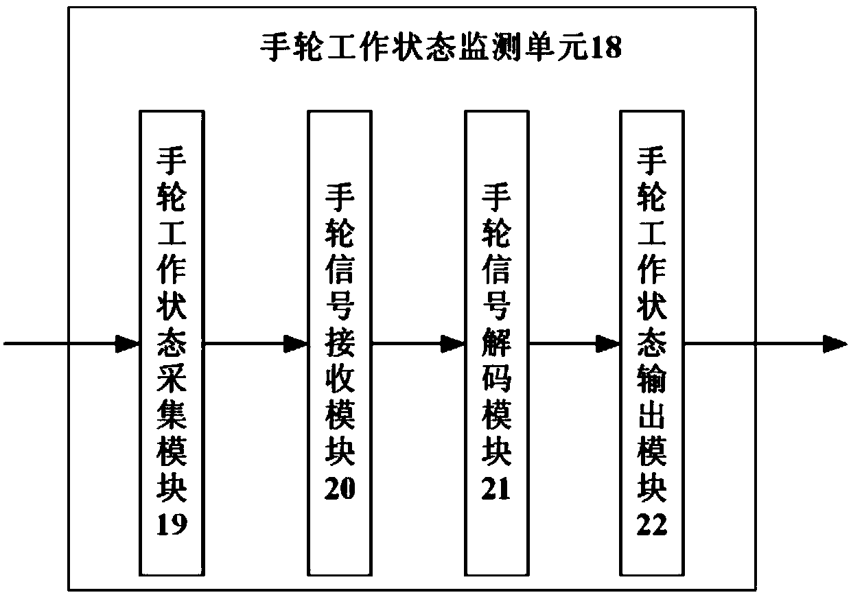
[0030] as attached figure 1 As shown, the present invention proposes a wire cutting equipment control device based on FPGA, which is provided with a host computer 1, a closed-loop control card 2, a motor driver 3, a motor 4, and a lead screw 5, wherein the motor 4 drives the lead screw to move, and the host computer 1 communicates with the closed-loop control card 2, and the closed-loop control card 2 communicates with the motor driver 3, and is characterized in that it is also provided with a grating ruler 6 for collecting the displacement data of the lead screw; the closed-loop control card 2 is provided with a closed-loop control unit 7, closed-loop The front end of the control unit 7 is provided with a signal decoding unit 8 for identifying and decoding the commands of the host computer, and the rear end of the closed-loop control unit 7 is provided with a coding o...


PUM


Abstract

The invention relates to an FPGA-based linear cutting device control device and method. The FPGA-based linear cutting device control device is provided with an upper computer, a closed loop control card, a motor driver, a motor and a lead screw, wherein the motor drives the lead screw to move, the upper computer communicates with the closed loop control card, and the closed loop control card communicates with the motor driver. The FPGA-based linear cutting device control device is characterized in that a grating ruler for collecting displacement data of the lead screw is further provided. Theclosed loop control card is provided with a closed loop control unit, the front end of the closed loop control unit is provided with a signal decoding unit for identifying and decoding the command ofthe upper computer, and the rear end of the closed loop control unit is provided with a code output unit for adapting to different types of motor drivers. A grating signal decoding unit is further provided, the input end of the grating signal decoding unit is connected to the output end of the grating ruler, and the output end of the grating signal decoding unit is connected with the closed loop control unit. The FPGA-based linear cutting device control device has the advantages of reasonable structure, high precision, high efficiency and stability.

Description

Technical field: [0001] The invention relates to the technical field of wire cutting machine control, in particular to an FPGA-based wire cutting equipment control device and method capable of realizing multi-axis independent control, fast control speed and high precision. Background technique: [0002] The wire cutting equipment drives the lead screw through the motor to drive the displacement of the molybdenum wire to realize cutting. At present, most domestic wire cutting equipment adopts open-loop control. The computer control card usually directly controls the driver of the motor. Due to the final fit accuracy error, the accuracy of the processed workpiece cannot be guaranteed. To this end, it is necessary to install a precision control device on the wire cutting equipment. The precision control device generally adopts a closed-loop control system, which aims to provide a system that can issue instructions from the host computer during work, and the stepping motor or m...

Claims


Application Information

Patent Timeline
Patent Type & Authority Applications(China)
IPC IPC(8): G05B19/042
CPCG05B19/0423G05B2219/21109Y02P90/02
Inventor 赵占锋于寿鹏万江华方恒阳李正军
Owner HARBIN INST OF TECH AT WEIHAI
Learn More