
A kind of optical module and communication equipment

An optical module and an integrated technology, applied in the field of optical communication, can solve the problems of increasing the cost of the whole machine, low reliability, and increasing the difficulty of assembly, and achieve the effects of reducing electromagnetic energy radiation, improving EMC problems, and optimizing EMC characteristics

Active Publication Date: 2020-06-30
HISENSE BROADBAND MULTIMEDIA TECH
View PDF5 Cites 0 Cited by
  • Summary
  • Abstract
  • Description
  • Claims
  • Application Information

AI Technical Summary

Problems solved by technology

[0003] When the electrical and electronic equipment in the optical module is working, there will be intermittent or continuous voltage and current changes, and sometimes the rate of change is quite fast, resulting in electromagnetic energy generated in different frequencies or between a frequency band, and the corresponding circuit will emit this energy to In the surrounding environment, on the one hand, there is signal radiation, which leaks out through the seams, slots, openings or other gaps in the shell; Free radiation in the space, which can cause interference and cause EMC problems
[0004] At present, two methods are mainly used to solve EMC problems. Method 1: Use shielding means to design and process structural components to be sufficiently sealed so that neither conduction radiation nor space radiation will leak, and internal devices will not be affected by external interference. , but limited by structural parts design, processing accuracy, matching of structural parts and devices, etc., it is unrealistic for structural parts to achieve an ideal sealing state in this way; Conductive foam and wave-absorbing materials are added to some parts of the parts. Conductive foam and wave-absorbing materials consume electromagnetic waves that affect the system by converting electromagnetic waves into heat energy. However, the addition of conductive foam and wave-absorbing materials in this way increases assembly Difficulty also increases the cost of the whole machine, and the improvement process requires repeated verification and sufficient assembly consistency, which has low reliability and is not conducive to mass production

Method used


Image

  • A kind of optical module and communication equipment
  • A kind of optical module and communication equipment

Examples


Embodiment Construction

[0022] The following will clearly and completely describe the technical solutions in the embodiments of the present invention with reference to the accompanying drawings in the embodiments of the present invention. Obviously, the described embodiments are only some, not all, embodiments of the present invention.

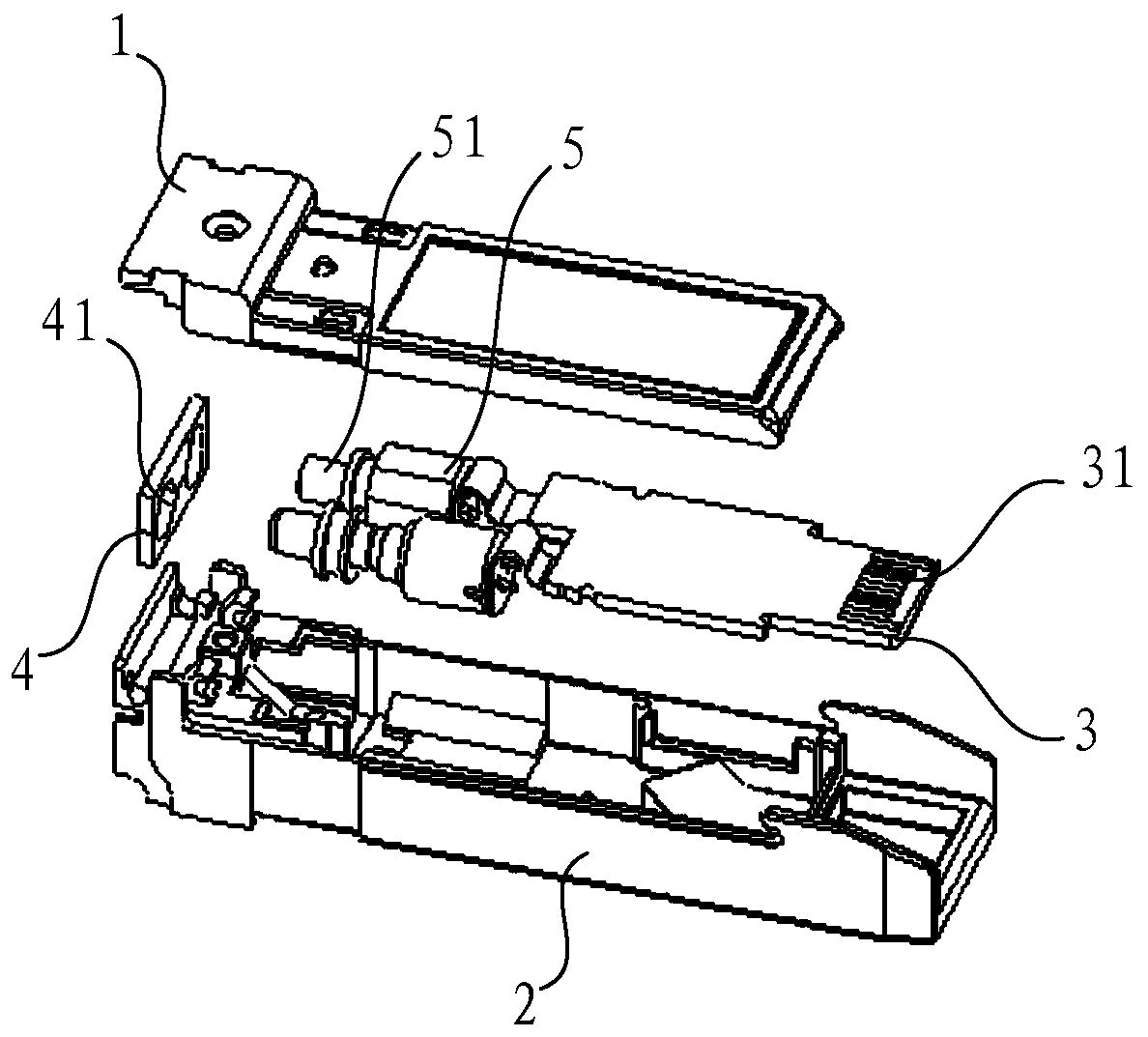
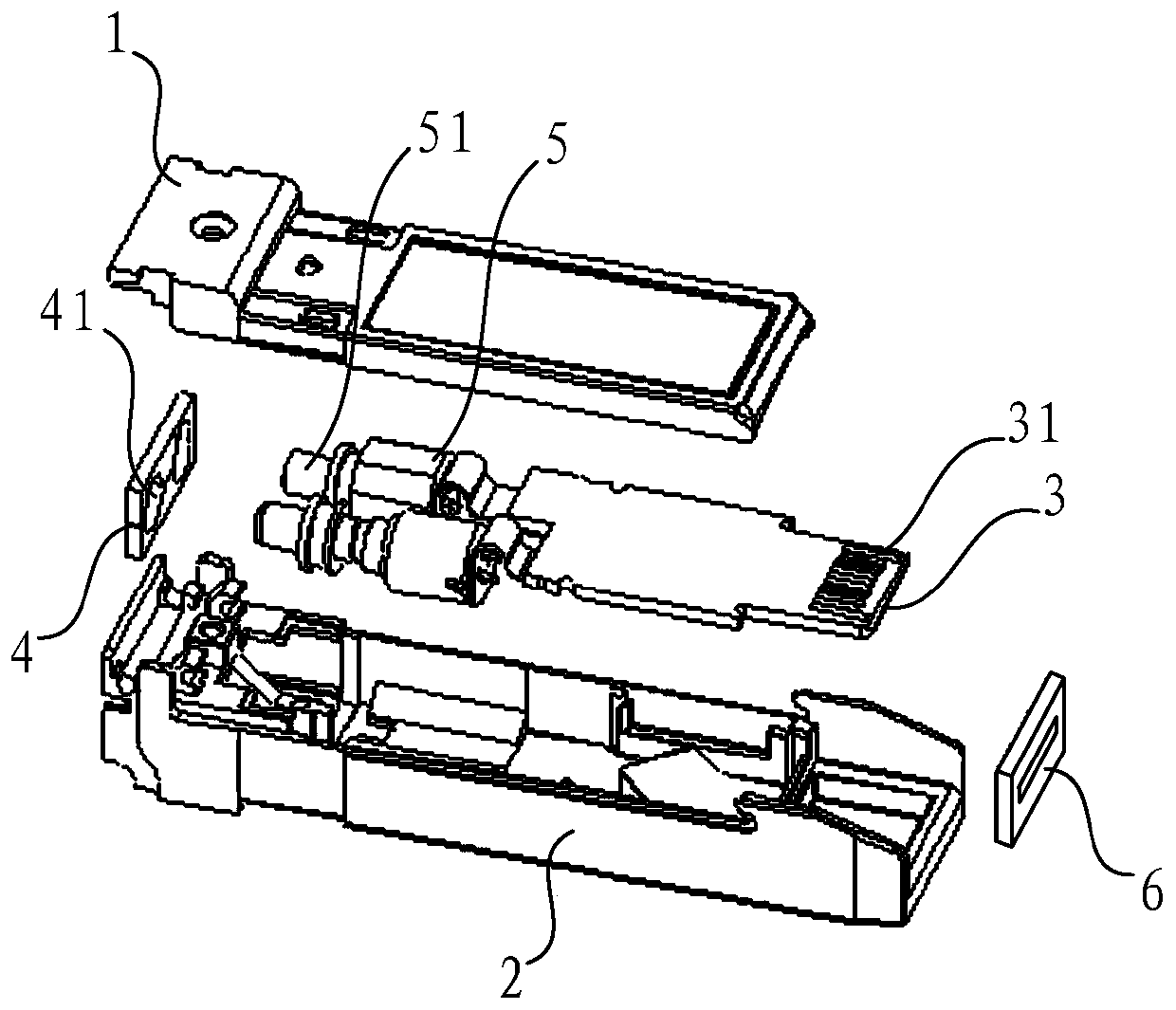
[0023] Such as figure 1 as well as figure 2 As shown, an optical module includes: an upper case 1, a lower case 2, an optical port 51 and an electrical port 31, and the upper case 1 and the lower case 2 form a space for accommodating the optical port 51 and the electrical port 31 In the holding chamber; also includes:

[0024] The first magnetic ring 4 is disposed in the accommodating cavity and located at the optical port 51 or the electrical port 31 , and the direction of the magnetic field of the first magnetic ring 4 is opposite to that of the magnetic field induced by electromagnetic waves.

[0025] The optical module provided by the present invention can eff...


PUM


Abstract

The invention discloses an optical module and communication equipment. The optical module comprises: an upper casing, a lower casing, an optical port and an electrical port, and the upper casing and the lower casing form a housing for accommodating the optical port and the electrical port. Cavity; also includes: a first magnetic ring, which is arranged in the accommodating cavity and is located at the optical port or the electrical port. The direction of the magnetic field of the first magnetic ring is opposite to that of the magnetic field induced by electromagnetic waves. By setting a first magnetic ring It can effectively and simply improve the EMC problem of the optical module, ensuring that the electromagnetic energy inside the optical module radiates outward and the external electromagnetic energy radiates to the inside of the optical module first through the first magnetic ring, so that the optical or electrical port The relative magnetic permeability at the place is reduced, thereby reducing the electromagnetic wave energy when the internal electromagnetic energy radiates outward and the external electromagnetic energy radiates to the inside of the optical module, thereby reducing the electromagnetic energy radiation around it and preventing the external electromagnetic energy from radiating to the inside of the optical module. radiation, thereby optimizing the EMC characteristics of the optical module and reducing electromagnetic interference.

Description

technical field [0001] The invention relates to the technical field of optical communication, in particular to an optical module and communication equipment. Background technique [0002] In the field of optical communication technology, EMC (Electro Magnetic Compatibility, electromagnetic compatibility) refers to the performance of a device that can work normally in its own environment without causing strong electromagnetic interference to any other devices in the environment. With the increase of density and distribution of operators, the requirements for EMC of optical modules are getting higher and higher. [0003] When the electrical and electronic equipment in the optical module is working, there will be intermittent or continuous voltage and current changes, and sometimes the rate of change is quite fast, resulting in electromagnetic energy generated in different frequencies or between a frequency band, and the corresponding circuit will emit this energy to In the su...

Claims


Application Information

Patent Timeline
Patent Type & Authority Patents(China)
IPC IPC(8): G02B6/42
CPCG02B6/4277
Inventor 段耀宇杨柳荫
Owner HISENSE BROADBAND MULTIMEDIA TECH
Learn More