
Vertically-arranged garbage incinerator

A waste incinerator and vertical arrangement technology, applied in the field of incinerators, can solve the problems of low utilization rate of equipment occupation, increase of equipment cost, low heat exchange efficiency, etc., to improve waste heat utilization efficiency, reduce equipment cost, reduce The effect of footprint

Pending Publication Date: 2018-10-19
光阳通泰环保设备有限公司
View PDF0 Cites 1 Cited by
  • Summary
  • Abstract
  • Description
  • Claims
  • Application Information

AI Technical Summary

Problems solved by technology

[0003] First, the horizontal grate furnace occupies a large area, resulting in a low utilization rate of the equipment, which is not conducive to saving costs;
[0004] Second, the flue gas generated by the combustion of the horizontal grate furnace needs to be extracted by the exhaust equipment, the resistance to be overcome is large, and the energy consumption is large, which is not conducive to reducing the cost;
[0005] Third, horizontal grate furnaces generally need to build high chimneys to discharge the treated flue gas generated by combustion, which not only increases the construction cost, but also is not beautiful, which is easy to cause the rejection of the public;
[0006] Fourth, the hearth of the horizontal grate furnace is short (0.8m ~ 1.0m), and it is impossible to realize the self-heating of the cold air blast. Generally, the flue gas generated by the combustion is extracted to exchange heat with the cold air, and the heat exchange is used to The final hot air blasts the furnace, the heat exchange efficiency is low, and the air temperature is low, which is not conducive to improving the combustion intensity, and increases the equipment cost

Method used


Image

  • Vertically-arranged garbage incinerator

Examples


Embodiment Construction

[0020] Below in conjunction with specific embodiment, further illustrate the present invention. It should be understood that these examples are only used to illustrate the present invention and are not intended to limit the scope of the present invention. In addition, it should be understood that after reading the teachings of the present invention, those skilled in the art can make various changes or modifications to the present invention, and these equivalent forms also fall within the scope defined by the appended claims of the present application.

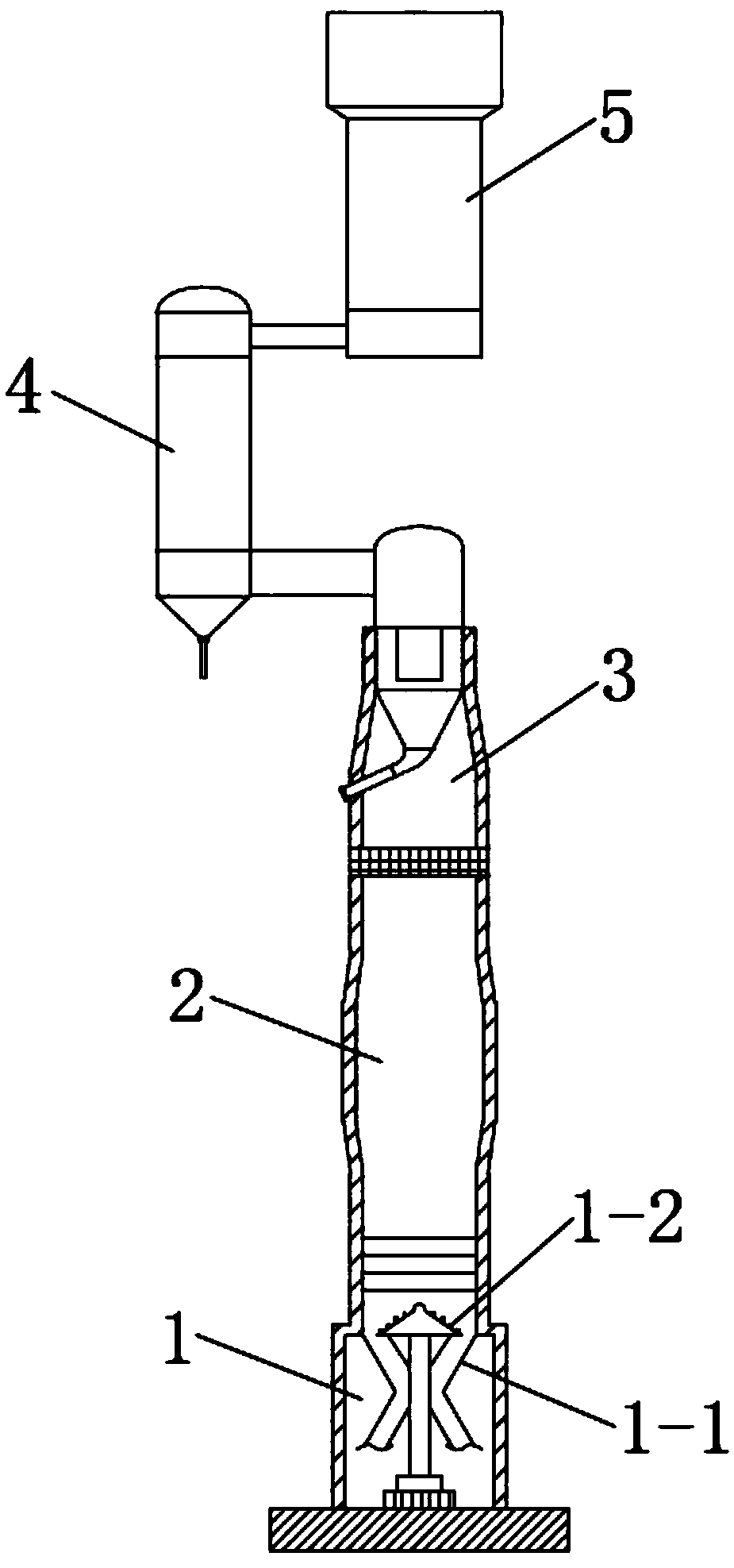
[0021] like figure 1 A vertically arranged garbage incinerator shown includes a blast slag discharge mechanism 1 , an incineration furnace 2 , a heat accumulator 3 , a waste heat exchanger 4 and a flue gas treatment system 5 .

[0022] The blowing slag removal mechanism 1 is arranged at the bottom of the incineration furnace 2 . The blast slagging mechanism 1 includes a slagging funnel 1-1 and a tower grate 1-2. The slagging...


PUM


Abstract

The invention relates to a vertically-arranged garbage incinerator. The vertically-arranged garbage incinerator comprises an air-blast slag discharging mechanism, an incineration hearth, a waste heatexchanger and a flue gas treatment system; the air-blast slag discharging mechanism is arranged at the bottom of the incineration hearth, the incineration hearth is cylindrical, the top of the incineration hearth is provided with a heat accumulator, the waste heat exchanger is arranged above the heat accumulator, and an air outlet of the heat accumulator communicates with a heat medium inlet of the waste heat exchanger; and the flue gas treatment system is arranged above the waste heat exchanger, and a heat medium outlet of the waste heat exchanger is connected to the flue gas treatment system. According to the garbage incinerator, the height space is fully utilized, the occupied area of equipment is greatly reduced, efficient combustion, energy conservation and environmental protection are achieved, and the garbage incinerator is beneficial to reducing the equipment cost and the using cost.

Description

technical field [0001] The invention belongs to the technical field of incinerators, in particular to a vertically arranged garbage incinerator. Background technique [0002] Most of the existing waste incinerators use horizontal grate furnaces, which mainly have the following disadvantages: [0003] First, the horizontal grate furnace occupies a large area, resulting in a low utilization rate of the equipment, which is not conducive to saving costs; [0004] Second, the flue gas generated by the combustion of the horizontal grate furnace needs to be extracted by the exhaust equipment, the resistance to be overcome is large, and the energy consumption is large, which is not conducive to reducing the cost; [0005] Third, horizontal grate furnaces generally need to build high chimneys to discharge the treated flue gas generated by combustion, which not only increases the construction cost, but also is not beautiful, which is easy to cause the rejection of the public; [000...

Claims


Application Information

Patent Timeline
Patent Type & Authority Applications(China)
IPC IPC(8): F23G5/24F23G5/44F23G5/46F23H15/00F23J1/06F23J15/02F23J15/04F23J15/06F23L15/00F22B1/18
CPCF22B1/18F23G5/245F23G5/44F23G5/46F23H15/00F23J1/06F23J15/02F23J15/04F23J15/06F23L15/00F23G2206/10F23G2206/20F23J2700/003Y02E20/34
Inventor 曹金福戚津华王贺丽
Owner 光阳通泰环保设备有限公司
Learn More