Anti-collision device for wharf

A technology for anti-collision devices and docks, applied in shipping equipment, climate change adaptation, etc., can solve problems such as poor buffering effect, damage to docks, easy damage of anti-collision devices, etc., and achieve improved anti-collision effects, improved service life, and buffering effects Good results

Inactive Publication Date: 2018-10-19
SHENYANG JIANZHU UNIVERSITY
View PDF0 Cites 0 Cited by
  • Summary
  • Abstract
  • Description
  • Claims
  • Application Information

AI Technical Summary

Problems solved by technology

However, the traditional anti-collision devices have many defects: no matter whether the ship passes the bridge or docks in the port, if the hull collides with the pier or wharf of the bridge, and after the hull docks at the wharf, due to the effect of the water flow, the hull There will be a certain relative movement with the anti-collision device, but the traditional anti-collision device did not take this into account in the design, resulting in the use of the anti-collision device, although it can well overcome the hull against the front of the wharf or pier. Impact force, but the force generated by the relative movement between the hull and the anti-collision device. The anti-collision device cannot resist the lateral force because there are no relevant measures in the design, so the anti-collision device is easily damaged, and eventually the anti-collision device The actual service life is always less than the design service life, and even causes damage to the wharf; in addition, the buffer layer set on the contact surface of the traditional anti-collision device is a smooth surface, and its buffer effect is poor when it contacts the hull.

Method used


Image

  • Anti-collision device for wharf
  • Anti-collision device for wharf
  • Anti-collision device for wharf

Examples


Embodiment

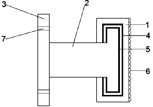
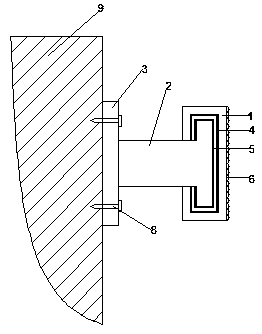
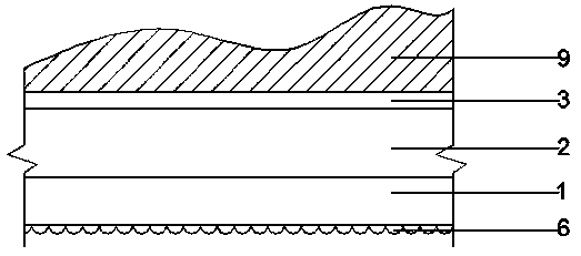
[0016] Example: such as Figure 1-3 Shown, a kind of wharf anti-collision device comprises buffer slide block 1, anti-collision column 2, installation substrate 3, magnet bar one 4, magnet bar two 5, buffer layer 6, mounting hole 7 and expansion bolt 8, and described buffer The longitudinal section shape of the slider 1 is C-shaped, the buffer layer 6 is set on the anti-collision contact surface of the buffer slider 1, and the magnet bar-4 is arranged on the inner surface of the buffer slider 1; the section shape of the buffer column 2 is T-shaped, and the section The outer surface of the larger end is provided with a magnet strip 2 5, the buffer slider 1 is sleeved on the larger side of the buffer column 2, and the smaller end of the buffer column 2 is fixedly connected with the installation substrate 3, and is set by the expansion bolt 8. On the side wall of the pier 9; the magnet strip one 4 and the magnet strip two 5 are of the same sex, and because the same sex repels eac...


PUM


Abstract

The invention relates to an anti-collision device for a wharf, and belongs to the field of wharf collision prevention. The device comprises a buffering sliding block, an anti-collision column and a mounting base plate, wherein the longitudinal section of the buffering sliding block is C-shaped; a buffering layer is arranged on an anti-collision contact surface of the buffering sliding bock; a first magnet strip is arranged on the inner side surface of the buffering sliding block; the buffering column is provided with a T-shaped section, and a second magnet strip is arranged on the outer surface of the end with big section of the buffering column; the buffering sliding block sleeves the side with big section of the buffering column, and the end with small section of the buffering column isfixedly connected to the mounting base plate and is arranged on the sidewall of the wharf. With the adoption of the anti-collision device for the wharf, the front impacting force of a ship body to thewharf can be effectively reduced, and moreover, the sliding block is arranged, so that the anti-collision device can move together with the ship body, thus the lateral force produced by relative moving of the ship body and the anti-collision device can be reduced, and as a result, the anti-collision device is prevented from damage caused by bearing lateral stress for a long term, and the servicelife of the anti-collision device is prolonged, and the anti-collision effect is improved.

Description

technical field [0001] The invention relates to a wharf anti-collision device, which belongs to the field of wharf anti-collision. Background technique [0002] In shipping docks, fishing ports, and places where ships are docked, in order to prevent the ship from colliding with the dock and being damaged, scrapped tires or other rubber objects are usually fixed on the side wall of the dock as an anti-collision shock-absorbing device. This anti-collision device It has a certain safety protection effect on the ship, and the cost is low. However, the traditional anti-collision devices have many defects: no matter whether the ship passes the bridge or docks in the port, if the hull collides with the pier or wharf of the bridge, and after the hull docks at the wharf, due to the effect of the water flow, the hull There will be a certain relative movement with the anti-collision device, but the traditional anti-collision device did not take this into account in the design, resulti...

Claims


Application Information

Patent Timeline
IPC IPC(8): E02B3/26
CPCE02B3/26Y02A30/30
Inventor 张延年周玲雪
Owner SHENYANG JIANZHU UNIVERSITY
Why Eureka
Try Eureka